c#: Traffic Lights Simulation via LEDs on Raspberry Pi
Introduction
This article will walk you through a small but fun tutorial simulating traffic lights. Here is how this is going to work:
- The red light turns ON for a specific time period
- The yellow light turns ON along with the red one
- After a couple of seconds only, the green light turns OFF and the red and yellow both turn OFF
- The green light stays on for a specific time period also
- When the time finishes, the green light goes OFF and the red light turns ON again
- The cycle repeats itself just like traffic signals do day and night
By the end of this tutorial, you will have successfully deployed a program which will be simulating the traffic signals just like on the roads. Please check out this article that explains the steps in getting started with the Pi if you're new along with essential requirements and a starter tutorial.
Requirements
- Windows 10 running Visual Studio 2015 (developer mode enabled)
- Raspberry Pi 2 with MicroSD Card having installed Windows 10 IoT Core
- 3 LEDs (red, yellow, green)
- 3 220? resistors
- Male - female jumper wires
- Male - male jumper wires
- Solderless Breadboard (I use half-size)
- Ethernet cable
Again, please do check out the other article (link above) if you still need to go through the installation and booting up process. Also, for the people in Pakistan, you can check out the online stores who can deliver you all this stuff at your doorstep. The links can be found in the same article.
Setting up the Breadboard
The diagram below is made using the free software Fritzing, which allows you to replicate your actual breadboard. The layout helps in creating the actual project.

We have used the LEDs and wires matching to the LED colors for the purpose of clarity and easy understanding. What you need to know before setting this us is that LEDs are diodes and a diode always allows electricity to pass in one way only so it is vital that you fix it in with the wires etc. correctly. The LED has two legs - one is shorter than the other one. The long leg is the positive side (cathode) and the short one is the negative side (anode) and goes to the 0v side. Another way to determine the positive and negative side is to look for a flat area around the LED. The flat part indicates that leg as negative and the other is then obviously the positive side. This is especially helpful if you've trimmed the legs of your LED.
The LEDs burn out really quickly if there is too much current flow. We need to pass current according to what the LED can take, otherwise, it will light up really bright for a little time and then it will burn out. We definitely do not want that to happen. For this purpose we will use a resistor. This will limit the current that flows though the LED making it light up bright enough but limited enough to not let it go to waste. For the purpose of this project 220? resistor is being used but you can use up to a 330? resistor too however avoid anything higher than that. It will only make the light dimmer. To sum it up, using a resistor less than the minimum will eventually burn out the LED and more than the maximum value will make the emitting light dimmer.
Let's set up the breadboard now. You will notice that there are blue and red lines on each long end of the breadboard. The blue usually represents ground (negative) and the red one represents power (positive) to make the work easier. The power and ground is supplied throughout the column and any wires connected there will have ground and power supply. The columns with alphabets are not connected like that. They are connected row-wise.
Let's give ground to the breadboard first. Connect the wire from physical Pin 6 (GND) on the Pi to one of the pin holes in the blue column. In the fritzing diagram shown above, the black wire represents Ground. That's it for this part.
Now take an LED, let's start with Red. Place it in the direction shown on the breadboard. Please make sure you're using the side of the breadboard where you've connected ground as the board is not completely connected.
Connect the long leg to GPIO 6 through the male-female jumper wire. Now connect one end of the resistor to the short leg and the other one in another row. Now connect the other end of the resistor to one of the pin holes in the ground column through male-male jumper wire. That's about it for the first LED.
Now repeat the process for the other two LEDs also. The pins to which you need to connect are:
Ground - Physical PIN 6, GND
Red - Physical PIN 29, GPIO 5
Yellow - Physical PIN 31, GPIO 6
Green - Physical PIN 33, GPIO 13
You will need to remember the GPIO numbers for the purpose of coding. Now let's move forward to lighting them up with our code.
UWP Application on VS 2015
First of all, open up Visual Studio and click on New Project.
Now select Templates > Visual C# > Windows > Universal and select the Blank App project. Give it a name, for example TrafficLightsSimulation and click OK.
Once the Solution Explorer opens up, you can start off with coding for your project. Because we will be working with LEDs, I did not make a visualization on XAML for this project, hence this project requires no HDMI cable attached to any external display.
Now navigate to MainPage.xaml.cs. Remember to add the Windows IoT Extensions for the UWP reference to your project because in order to code and control the LEDS through GPIO pins, we need to reference the namespace Windows.Devices.Gpio.
In `public sealed partial class MainPage: Page' section, declare all the variables that you need for the GPIO pins, the timer, and a variable to let the simulation flow in a continuous loop.
public sealed  partial class  MainPage : Page
 {
 private GpioPin redLED;
 private GpioPin yellowLED;
 private GpioPin greenLED;

 private DispatcherTimer timer;
 private int  loop = 0;
In public MainPage() let's call a method to initialize the LEDS. By default they are set to input and we need to set them to output.
public MainPage()
 {
 this.InitializeComponent();
 InitializeLed();
Now create a private void method and initialize the LEDs to output mode and by default OFF when we deploy the code:
private void  InitializeLed()
 {
 var gpio = GpioController.GetDefault();

 redLED = gpio.OpenPin(5);
 redLED.SetDriveMode(GpioPinDriveMode.Output);
 yellowLED = gpio.OpenPin(6);
 yellowLED.SetDriveMode(GpioPinDriveMode.Output);
 greenLED = gpio.OpenPin(13);
 greenLED.SetDriveMode(GpioPinDriveMode.Output);

 OffLED(redLED);
 OffLED(yellowLED);
 OffLED(greenLED);

 }
This code sets the GPIO pins to the integer values and then sets their mode to output. It then calls the OffLED method which sets the pins to low value which means that they will be turned off when the program is executed. Let's look at the OffLED and OnLED methods, both take a single argument:
private void  OnLED(GpioPin pin)
 {
 pin.Write(GpioPinValue.High);
 }

private void  OffLED(GpioPin pin)
 {
 pin.Write(GpioPinValue.Low);
 }
The OnLED method sets the pin to High which means the LED will turn on i.e. emit light. Now go back to public MainPage() and add code for setting and starting the timer along with event handler LedBlinking to execute the simulation:
public MainPage()
{
 this.InitializeComponent();
 InitializeLed();

 timer = new  DispatcherTimer();
 timer.Interval = TimeSpan.FromMilliseconds(1000);
 timer.Tick += LedBlinking;
 timer.Start();

}
The timer ticks every second. The LedBlinking method has the code to simulate the traffic lights with LEDs in a loop using the loop variable. The switch case number determines the delay in the turning on and off routines between the LEDs. For example, it switches from case 1 to case 4 which means case 4 will cause the yellow light to light up after 3 ticks from the time that the red one lights up.
private void  LedBlinking(object sender, object e)
 {
 switch (loop)
 {
 case 1:
 OnLED(redLED);
 break;
 case 3:
 OnLED(yellowLED);
 break;
 case 5:
 OffLED(redLED);
 OffLED(yellowLED);
 OnLED(greenLED);
 break;
 case 9:
 OnLED(redLED);
 OffLED(yellowLED);
 OffLED(greenLED);
 loop = 0;
 break;
 }
 loop++;
 }
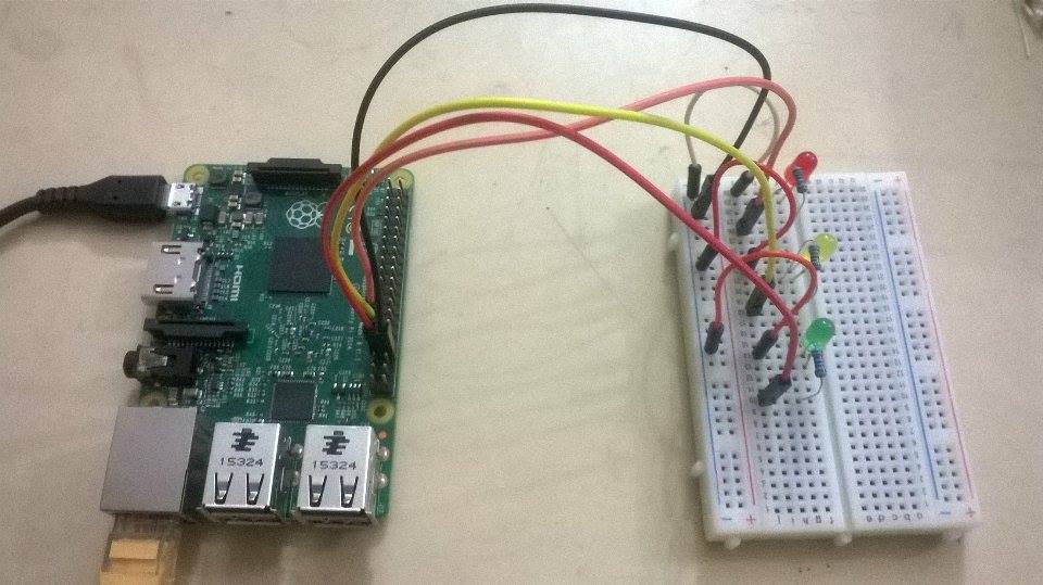
That's it for the code. Now you can deploy your project and see how it works. In the image below, I've connected ground with physical pin 34 unlike the fritzing diagram, it doesn't matter as long as it is ground.
Here's the video of the code in execution just to give you guys the basic idea of it (this was made after first deployment so timings are a little messed up),