Small Basic: Simpler and Cheaper Raspberry Pi GPIO
Introduction
In my previous article (http://social.technet.microsoft.com/wiki/contents/articles/30188.small-basic-and-the-raspberry-pi.aspx), I described using a Raspberry Pi Model A+ as a GPIO (General Purpose Input/Output) controller for Microsoft Small Basic, accessible over a network connection. That setup required the following equipment:
- Raspberry Pi Model A+ ($20 USD)
- Micro-SD card ($5)
- Micro-USB power supply ($5)
- USB wireless network interface ($10)
- Adafruit T-Cobbler Plus breakout board ($10)
- Solderless breadboard ($3)
for a total of just over $50, depending on how much we might already have.
Since that time, the Raspberry Pi Zero (Figure 1), with a retail price of just $5 has been released. If one is willing to forgo wireless operation, a much simpler and cheaper GPIO controller can be assembled. It is possible use a single USB cable to simultaneously supply power and communicate with a Raspberry Pi Zero, by changing the Linux kernel to configure the Raspberry Pi's USB port as a USB device instead of a USB host.
http://tech.munts.com/SmallBasic/Examples/RaspberryPiGPIOGadget/_figures/Figure1-RaspberryPiZeroUSBDevice.jpg
Figure 1 -- Raspberry Pi Zero USB Device
Now only the following equipment is required:
- Raspberry Pi Zero ($5)
- Header pins or socket ($2)
- Micro SD card ($5)
- Micro USB cable ($2)
- Adafruit T-Cobbler Plus breakout board ($10)
- Solderless breadboard ($3)
for a total equipment price of $27, about half of the previous total price.
Note: This USB device mode also works on both the Raspberry Pi Model A+ and the older Model A, if we use a special USB cable with male type-A plugs on both ends. At time of writing the Raspberry Pi Zero is still hard to get and remains back-ordered at many suppliers. We may find it easier to obtain a Model A+. The Raspberry Pi firmware described in this article runs on any of the Raspberry Pi Model A, A+, or Zero, but not on any Model B (i.e. B, B+, 2 B, 3 B).
Linux USB Ethernet Gadget
As with the previous system using the Raspberry Pi Model A+, the Raspberry Pi Zero runs a dedicated GPIO server built with MuntsOS, a very small Linux distribution for embedded systems. However, instead of the normal Linux network stack for wired or wireless Ethernet, the Linux kernel configures the Raspberry Pi Zero USB port as a so-called “USB Gadget”. There are several different kinds of USB Gadgets selectable in the Linux kernel, including serial port, mouse, storage, and Ethernet.
The Ethernet Gadget is perhaps most interesting, as it permits network communication between the USB host (a Windows, MacOS, or Linux computer) and the USB device (the Raspberry Pi Zero). When we connect a cable between our host computer and the Raspberry Pi Zero, the host computer will recognize its end of the connection as a USB Ethernet device, and create a network interface for it.
The MuntsOS Linux environment running on the Raspberry Pi Zero also recognizes its end of the USB connection as an Ethernet device. It configures a fixed network address on its interface and runs a DHCP (Dynamic Host Configuration Protocol) server to configure the dynamically configure the network address on the host computer.
By default, the Raspberry Pi Zero configures its own IP address to 10.254.254.252 and the host computer’s IP address to 10.254.254.253. These addresses can be changed by editing the file cmdline.txt on the micro-SD card, but that will almost never be necessary unless we need to plug more than one Raspberry Pi Zero into a single host computer.
Like the GPIO controller described in the previous article, the Raspberry Pi Zero also starts an MDNS (Multicast Domain Name Service) responder and registers it self as usbgadget.local. If our computer has Internet access, the domain name usbgadget.munts.net also resolves to 10.254.254.252.
Test Setup
1. Download the MuntsOS GPIO Thin Server zip file:
http://repo.munts.com/muntsos/thinservers/muntsos-gpio-server-RaspberryPiGadget.zip
- Unzip it to a freshly formatted micro-SD card.
3. Insert the micro-SD card in the Raspberry Pi Zero.
4. Connect a micro-USB cable from our host computer to the Raspberry Pi Zero. Be sure the plug into the middle socket labeled USB, not the rightmost socket labeled PWR.
As with the Raspberry Pi A+ in the previous article, I connected the Raspberry Pi Zero to a T-Cobbler Plus break board inserted into a solderless breadboard. Unlike other Raspberry Pi models, the Zero does not come with header pins soldered into the expansion bus. We can either solder male pins on top of the board, for connecting a ribbon cable or “hat” expansion board, or we can solder a female socket on the bottom of the board and mount the zero directly onto a male pin header like that on the T-Cobbler Plus (Figure 2).
http://tech.munts.com/SmallBasic/Examples/RaspberryPiGPIOGadget/_figures/Figure2-BreadboardSetup.jpg
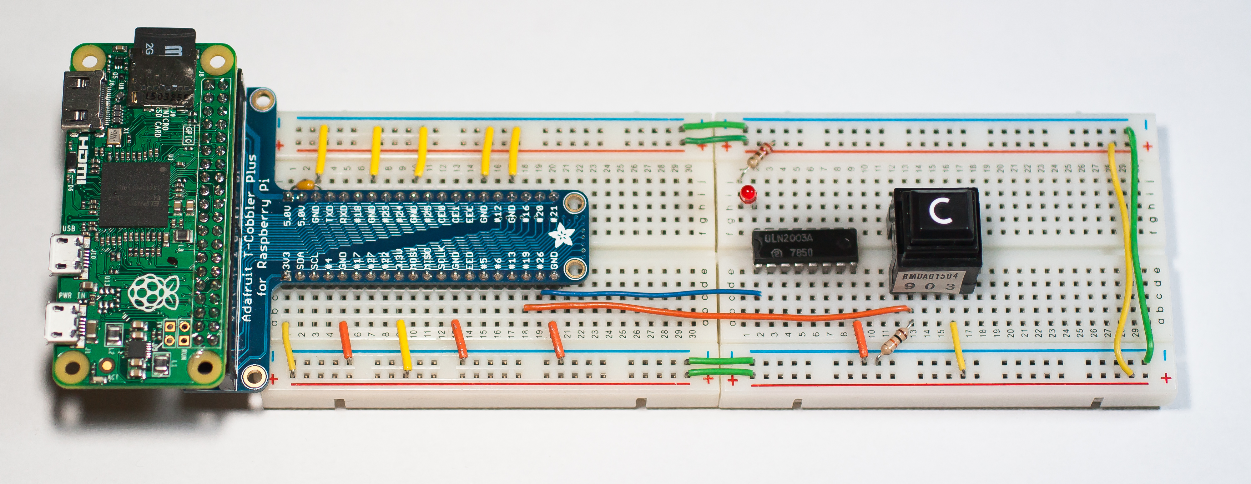
Figure 2 -- Test Setup
Test Program
The Small Basic test program from the previous article, published as PCD388-0, works with this test setup as well, by entering usbgadget.munts.net or usbgadget.local for the server name.
A new test program, published as SDW438-0, illustrates how to read from a switch on a GPIO input and write to an LED on a GPIO output. This new test program also has some other improvements, including accepting ENTER in the text box as a completion signal, and moving all network code from the event handlers to the main thread to improve user interface responsiveness.