Create a remote network with a custom IKE policy for Global Secure Access
IPSec tunnel is a bidirectional communication. This article provides the steps to set up the communication channel in Microsoft Entra admin center and the Microsoft Graph API. The other side of the communication is configured on your customer premises equipment (CPE).
Prerequisites
To create a remote network with a custom Internet Key Exchange (IKE) policy, you must have:
- A Global Secure Access Administrator role in Microsoft Entra ID.
- Received the connectivity information from Global Secure Access onboarding.
- The product requires licensing. For details, see the licensing section of What is Global Secure Access. If needed, you can purchase licenses or get trial licenses.
How to create a remote network with a custom IKE policy
If you prefer to add custom IKE policy details to your remote network, you can do so when you add the device link to your remote network. You can complete this step in the Microsoft Entra admin center or using the Microsoft Graph API.
To create a remote network with a custom IKE policy in the Microsoft Entra admin center:
Sign in to the Microsoft Entra admin center as a Global Secure Access Administrator.
Browse to Global Secure Access > Connect > Remote networks.
Select Create remote network.
Provide a name and region for your remote network and select Next: Connectivity.
Select + Add a link to add the connectivity details of your CPE.
Add a link - General tab
There are several details to enter on the General tab. Pay close attention to the Peer and Local Border Gateway Protocol (BGP) addresses. The peer and local details are reversed, depending on where the configuration is completed.
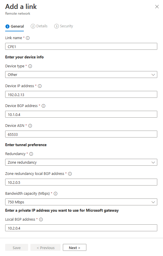
Enter the following details:
- Link name: Name of your CPE.
- Device type: Choose a device option from the dropdown list.
- Device IP address: Public IP address of your device.
- Device BGP address: Enter the BGP IP address of your CPE.
- This address is entered as the local BGP IP address on the CPE.
- Device ASN: Provide the autonomous system number (ASN) of the CPE.
- A BGP-enabled connection between two network gateways requires that they have different ASNs.
- Refer to the valid ASN values list for reserved values that can't be used.
- Redundancy: Select either No redundancy or Zone redundancy for your IPSec tunnel.
- Zone redundancy local BGP address: This optional field shows up only when you select Zone redundancy.
- Enter a BGP IP address that isn't part of your on-premises network where your CPE resides and is different from Local BGP address.
- Bandwidth capacity (Mbps): Specify tunnel bandwidth. Available options are 250, 500, 750, and 1,000 Mbps.
- Local BGP address: Enter a BGP IP address that isn't part of your on-premises network where your CPE resides.
- For example, if your on-premises network is 10.1.0.0/16, then you can use 10.2.0.4 as your Local BGP address.
- This address is entered as the peer BGP IP address on your CPE.
- Refer to the valid BGP addresses list for reserved values that can't be used.
Select the Next.
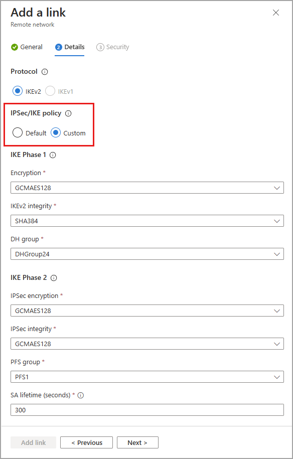
Add a link - Details tab
Important
You must specify both a Phase 1 and Phase 2 combination on your CPE.
IKEv2 is selected by default. Currently only IKEv2 is supported.
Change the IPSec/IKE policy to Custom.
Select your Phase 1 combination details for Encryption, IKEv2 integrity, and DHGroup.
- The combination of details you select must align with the available options listed in the Remote network valid configurations reference article.
Select your Phase 2 combinations for IPsec encryption, IPsec integrity, PFS group, and SA lifetime (seconds).
- The combination of details you select must align with the available options listed in the Remote network valid configurations reference article.
Whether you choose Default or Custom, the IPSec/IKE policy you specify must match the crypto policy on your CPE.
Select Next.
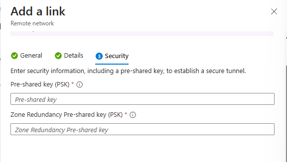
Add a link Security tab
- Enter the Pre-shared key (PSK) and Zone Redundancy Pre-shared key (PSK). The same secret key must be used on your respective CPE. The Zone Redundancy Pre-shared key (PSK) field only appears if redundancy is set on the first page in creating the link.
- Select Save.