Topology Pins
The WDMAud system driver translates topology pins on KS filters into the source and destination mixer lines that the mixer API exposes to applications. Input (sink) pins become source mixer lines, and output (source) pins become destination mixer lines.
As described in Pin Factories, a miniport driver provides an array of pin descriptors, each of which is a structure of type PCPIN_DESCRIPTOR that describes a pin factory belonging to a filter. Each pin descriptor includes the following information:
Dataflow direction specifier
Indicates whether the data stream enters (KSPIN_DATAFLOW_IN) or exits (KSPIN_DATAFLOW_OUT) the filter through the pin.
KS pin category GUID
Indicates the pin category to which the pin belongs. For example, on an audio playback device, one pin might accept a wave-formatted digital audio stream, and another pin might generate an analog audio signal to drive a speaker. The miniport driver identifies these two types of pins as belonging to distinct pin categories.
Communications type specifier
Indicates the type of IRP communications that the pin supports. A pin that supports IRP communications can be an IRP sink (KSPIN_COMMUNICATION_SINK), IRP source (KSPIN_COMMUNICATION_SOURCE), or both (KSPIN_COMMUNICATION_BOTH). A pin that does not support IRP communications can either lie inside a KS filter graph (KSPIN_COMMUNICATION_NONE) or be a bridge pin at the endpoint of a graph (KSPIN_COMMUNICATION_BRIDGE).
For more information about bridge pins, see Audio Filter Graphs.
WDMAud converts the information from the miniport driver's pin descriptor into a mixer-line descriptor, which is a structure of type MIXERLINE that includes the following information:
Mixer-line component type
Indicates whether the mixer line is a source or a destination line, and also indicates the general function of the mixer line. For example, the component type for a mixer line that transports an analog signal that is generated from a wave output (rendering) stream to drive a set of headphones is MIXERLINE_COMPONENTTYPE_DST_HEADPHONES.
Mixer-line target type
Indicates the type of data stream that the mixer line transports. For example, the target type for a wave output (rendering) stream is MIXERLINE_TARGETTYPE_WAVEOUT, and the target type for a wave input (capture) stream is MIXERLINE_TARGETTYPE_WAVEIN.
For more information, see the MIXERLINE structure in the SDK documentation.
The following two tables show how WDMAud translates input (KSPIN_DATAFLOW_IN) pins source mixer lines.
The first table shows how the input pin KS pin category GUIDs (PCPIN_DESCRIPTOR values) map to the associated MIXERLINE target types.
| KS pin category GUID | Bridge pin? | MIXERLINE Target type |
|---|---|---|
| KSNODETYPE_MICROPHONE | - | MIXERLINE_TARGETTYPE_WAVEIN |
| KSNODETYPE_DESKTOP_MICROPHONE | - | MIXERLINE_TARGETTYPE_WAVEIN |
| KSNODETYPE_LEGACY_AUDIO_CONNECTOR | - | MIXERLINE_TARGETTYPE_WAVEOUT |
| KSCATEGORY_AUDIO | - | MIXERLINE_TARGETTYPE_WAVEOUT |
| KSNODETYPE_SPEAKER | - | MIXERLINE_TARGETTYPE_WAVEOUT |
| KSNODETYPE_CD_PLAYER | - | MIXERLINE_TARGETTYPE_UNDEFINED |
| KSNODETYPE_SYNTHESIZER | - | MIXERLINE_TARGETTYPE_MIDIOUT |
| KSNODETYPE_LINE_CONNECTOR | - | MIXERLINE_TARGETTYPE_UNDEFINED |
| KSNODETYPE_TELEPHONE | - | MIXERLINE_TARGETTYPE_UNDEFINED |
| KSNODETYPE_PHONE_LINE | - | MIXERLINE_TARGETTYPE_UNDEFINED |
| KSNODETYPE_DOWN_LINE_PHONE | - | MIXERLINE_TARGETTYPE_UNDEFINED |
| KSNODETYPE_ANALOG_CONNECTOR | Yes | MIXERLINE_TARGETTYPE_WAVEIN |
| KSNODETYPE_ANALOG_CONNECTOR | No | MIXERLINE_TARGETTYPE_WAVEOUT |
| KSNODETYPE_SPDIF_INTERFACE | Yes | MIXERLINE_TARGETTYPE_WAVEIN |
| KSNODETYPE_SPDIF_INTERFACE | No | MIXERLINE_TARGETTYPE_WAVEOUT |
The following table shows how the input pin KS pin category GUIDs map to the associated MIXERLINE component types.
| PCPIN_DESCRIPTOR values | MIXERLINE values |
|---|---|
| KS pin category GUID | Component type |
KSNODETYPE_MICROPHONE KSNODETYPE_DESKTOP_MICROPHONE |
MIXERLINE_COMPONENTTYPE_SRC_MICROPHONE |
KSNODETYPE_LEGACY_AUDIO_CONNECTOR KSCATEGORY_AUDIO KSNODETYPE_SPEAKER |
MIXERLINE_COMPONENTTYPE_SRC_WAVEOUT |
KSNODETYPE_CD_PLAYER |
MIXERLINE_COMPONENTTYPE_SRC_COMPACTDISC |
KSNODETYPE_SYNTHESIZER |
MIXERLINE_COMPONENTTYPE_SRC_SYNTHESIZER |
KSNODETYPE_LINE_CONNECTOR |
MIXERLINE_COMPONENTTYPE_SRC_LINE |
KSNODETYPE_TELEPHONE KSNODETYPE_PHONE_LINE KSNODETYPE_DOWN_LINE_PHONE |
MIXERLINE_COMPONENTTYPE_SRC_TELEPHONE |
KSNODETYPE_ANALOG_CONNECTOR |
MIXERLINE_COMPONENTTYPE_SRC_ANALOG |
KSNODETYPE_ANALOG_CONNECTOR |
MIXERLINE_COMPONENTTYPE_SRC_ANALOG |
KSNODETYPE_SPDIF_INTERFACE |
MIXERLINE_COMPONENTTYPE_SRC_DIGITAL |
KSNODETYPE_SPDIF_INTERFACE |
MIXERLINE_COMPONENTTYPE_SRC_DIGITAL |
In the preceding tables, the left column specifies the pin category GUID from the pin's PCPIN_DESCRIPTOR structure, and the right columns specify the corresponding target type and component type for the MIXERLINE structure.
The entries in the column labeled "Bridge Pin?" indicate whether the pin is a bridge pin. A "Yes" means that the pin communications type is KSPIN_COMMUNICATION_BRIDGE. A "No" means that the pin communications type is a KSPIN_COMMUNICATION_Xxx value other than KSPIN_COMMUNICATION_BRIDGE. If WDMAud ignores the pin communications type when translating the pin parameters to mixer-line parameters, the "Bridge Pin?" entry is a dash (-).
For all pin categories that do not appear in the preceding tables, WDMAud translates the input pins to source mixer lines with target types of MIXERLINE_TARGETTYPE_UNDEFINED and component types of MIXERLINE_COMPONENTTYPE_SRC_UNDEFINED.
The following tables show how WDMAud translates output (KSPIN_DATAFLOW_OUT) pins to destination mixer lines. The column headings have the same meanings as in the preceding table. The first table shows how the output pin KS pin category GUIDs map to the associated MIXERLINE target types.
| KS pin category GUID | Bridge pin? | MIXERLINE Target type |
|---|---|---|
| KSNODETYPE_SPEAKER | - | MIXERLINE_TARGETTYPE_WAVEOUT |
| KSNODETYPE_DESKTOP_SPEAKER | - | MIXERLINE_TARGETTYPE_WAVEOUT |
| KSNODETYPE_ROOM_SPEAKER | - | MIXERLINE_TARGETTYPE_WAVEOUT |
| KSNODETYPE_COMMUNICATION_SPEAKER | - | MIXERLINE_TARGETTYPE_WAVEOUT |
| KSCATEGORY_AUDIO | - | MIXERLINE_TARGETTYPE_WAVEIN |
| PINNAME_CAPTURE | - | MIXERLINE_TARGETTYPE_WAVEIN |
| KSNODETYPE_HEADPHONES | - | MIXERLINE_TARGETTYPE_WAVEOUT |
| KSNODETYPE_HEAD_MOUNTED_DISPLAY_AUDIO | - | MIXERLINE_TARGETTYPE_WAVEOUT |
| KSNODETYPE_TELEPHONE | - | MIXERLINE_TARGETTYPE_UNDEFINED |
| KSNODETYPE_PHONE_LINE | - | MIXERLINE_TARGETTYPE_UNDEFINED |
| KSNODETYPE_DOWN_LINE_PHONE | - | MIXERLINE_TARGETTYPE_UNDEFINED |
| KSNODETYPE_ANALOG_CONNECTOR | Yes | MIXERLINE_TARGETTYPE_WAVEOUT |
| KSNODETYPE_ANALOG_CONNECTOR | No | MIXERLINE_TARGETTYPE_WAVEIN |
| KSNODETYPE_SPDIF_INTERFACE | Yes | MIXERLINE_TARGETTYPE_WAVEOUT |
| KSNODETYPE_SPDIF_INTERFACE | No | MIXERLINE_TARGETTYPE_WAVEIN |
The following table shows how the output pin KS pin category GUIDs map to the associated MIXERLINE component types.
| PCPIN_DESCRIPTOR values | MIXERLINE values |
|---|---|
| KS pin category GUID | Component type |
KSNODETYPE_SPEAKER KSNODETYPE_DESKTOP_SPEAKER KSNODETYPE_ROOM_SPEAKER KSNODETYPE_COMMUNICATION_SPEAKER |
MIXERLINE_COMPONENTTYPE_DST_SPEAKERS |
KSCATEGORY_AUDIO PINNAME_CAPTURE |
MIXERLINE_COMPONENTTYPE_DST_WAVEIN |
KSNODETYPE_HEADPHONES KSNODETYPE_HEAD_MOUNTED_DISPLAY_AUDIO |
MIXERLINE_COMPONENTTYPE_DST_HEADPHONES |
KSNODETYPE_TELEPHONE KSNODETYPE_PHONE_LINE KSNODETYPE_DOWN_LINE_PHONE |
MIXERLINE_COMPONENTTYPE_DST_TELEPHONE |
KSNODETYPE_ANALOG_CONNECTOR |
MIXERLINE_COMPONENTTYPE_DST_SPEAKERS |
KSNODETYPE_ANALOG_CONNECTOR |
MIXERLINE_COMPONENTTYPE_DST_WAVEIN |
KSNODETYPE_SPDIF_INTERFACE |
MIXERLINE_COMPONENTTYPE_DST_SPEAKERS |
KSNODETYPE_SPDIF_INTERFACE |
MIXERLINE_COMPONENTTYPE_DST_WAVEIN |
For all pin categories that do not appear in the preceding tables, WDMAud translates the output pins to destination mixer lines with target types of MIXERLINE_TARGETTYPE_UNDEFINED and component types of MIXERLINE_COMPONENTTYPE_DST_UNDEFINED.
In the preceding tables, most of the KS pin category GUIDs have KSNODETYPE_Xxx names. These names are defined in header files Ksmedia.h and Dmusprop.h. (Two departures from this naming convention are GUIDs KSCATEGORY_AUDIO and PINNAME_CAPTURE, which are also defined in Ksmedia.h.) As described in Topology Nodes, KSNODETYPE_Xxx GUIDs can also be used to designate KS node types. Most KSNODETYPE_Xxx GUIDs specify either pin categories or node types, but not both. The exception is KSNODETYPE_SYNTHESIZER, which can specify either a pin category or a node type, depending on the context in which is used. For a list of KSNODETYPE_Xxx GUIDs representing pin categories, see Pin Category Property. For a list of KSNODETYPE_Xxx GUIDs representing node types, see Audio Topology Nodes.
KSCATEGORY_AUDIO is another dual-usage GUID. It can be used as either a KS pin category GUID or a KS filter category GUID, depending on the context. During device installation, an audio driver registers its device interface under the filter category KSCATEGORY_AUDIO. For more information, see Installing Device Interfaces for an Audio Adapter.
For a pin category of KSNODETYPE_ANALOG_CONNECTOR or KSNODETYPE_SPDIF_INTERFACE, WDMAud needs to know whether the pin is a bridge pin to correctly translate the pin to its mixer-line equivalent. For example, an S/PDIF pin (with pin category KSNODETYPE_SPDIF_INTERFACE) translates to one of the four mixer-line types shown in the following figure. The translation depends on both the pin's data direction (in or out) and whether it is a bridge pin (yes or no), which together yield four possible types of mixer line (in+yes, in+no, out+yes, and out+no). The four mixer-line types shown in the figure represent the bottom pairs of entries from the preceding tables.
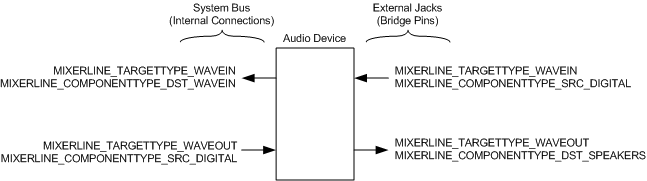
Note that two streams on the right side of the audio device in the figure are in S/PDIF format, and the two streams on the left are in wave format. The audio device performs the conversion between the two digital formats.
The SndVol32 application is a client of the mixer API. The mixer API converts each pin found in the topology to either a source or destination mixer line, but the line might not be shown in SndVol32, which recognizes only a subset of the mixer-line component types that header file Mmsystem.h defines for the mixer API. For more information about SndVol32, see SysTray and SndVol32.