How to configure NIC Teaming with HP Proliant and Cisco or Procurve Switch Infrastructure?
Very often I do need to configure NIC teams with HP hardware with Cisco or Procurve networking infrastructure therefore I would like to share an general overview of the NIC HP teaming capabilities, general teaming algorithms and especially how to configure an Cisco or Procurve switches.
My personal preferred teaming mode here is to use the 802.3ad teaming mode as it provides most redundancy and performance throughput capabilities and is the current industry standard which is well understood by enterprise switches.
HP generally provides following NIC teaming capabilities and algorithms:
1.1 Network Fault Tolerance (NFT) only - Network Fault Tolerance (NFT) is the foundation of HP ProLiant Network Adapter Teaming. In NFT mode, from two to eight teamed ports are teamed together to operate as a single virtual network adapter. However, only one teamed port—the primary teamed port—is used for both transmit and receive communication with the server. The remaining adapters are considered to be stand-by (or secondary adapters) and are referred to as non-primary teamed ports. Non-primary teamed ports remain idle unless the primary teamed port fails. All teamed ports may transmit and receive heartbeats, including non-primary adapters.
The fault-tolerance feature that NFT represents for HP ProLiant Network Adapter Teaming is the only feature found in every other team type. The foundation of every team type supports NFT.
1.2 Network Fault Tolerance (NFT) with Preference Order - Network Fault Tolerance Only with Preference Order is identical in almost every way to NFT with the only difference being that this team type allows the SA to prioritize the order in which teamed ports should be the primary teamed port. This ability is important in environments where one or more teamed ports are more preferred than other ports in the same team. The need for ranking certain teamed ports better than others can be a result of unequal speeds, better adapter capabilities (for example, higher receive/transmit descriptors or buffers, interrupt coalescence, and so on), or preference for the team’s primary port to be located on a specific switch.
1.3 Transmit Load Balancing (TLB) with Fault Tolerance - Transmit Load Balancing with Fault Tolerance (TLB) is a team type that allows the server to load balance its transmit traffic. TLB is switch independent and supports switch fault tolerance by allowing the teamed ports to be connected to more than one switch in the same LAN. With TLB, traffic received by the server is not load balanced. The primary teamed port is responsible for receiving all traffic destined for the server. In case of a failure of the primary teamed port, the NFT mechanism ensures connectivity to the server is preserved by selecting another teamed port to assume the role.
1.4 Transmit Load Balancing (TLB) with Fault Tolerance and Preference Order - Transmit Load Balancing with Fault Tolerance and Preference Order is identical in almost every way to TLB with the only difference being that this team type allows the SA to prioritize the order in which teamed ports should be the primary teamed port. This ability is important in environments where one or more teamed ports are more preferred than other ports in the same team. The need for ranking certain teamed ports higher than others can be a result of unequal speeds, better adapter capabilities (for example, higher receive/transmit descriptors or buffers, interrupt coalescence, and so on), or preference for the team’s primary port to be located on a specific switch.
1.5 Switch-assisted Load Balancing (SLB) with Fault Tolerance - Switch-assisted Load Balancing with Fault Tolerance (SLB) is a team type that allows full transmit and receive load balancing. SLB requires the use of a switch that supports some form of Port Trunking (for example, EtherChannel, MultiLink Trunking, and so on). SLB does not support switch redundancy because all ports in a team must be connected to the same switch. SLB is similar to the 802.3ad Dynamic team type.
1.6 802.3ad Dynamic with Fault Tolerance - 802.3ad Dynamic with Fault Tolerance is identical to SLB except that the switch must support the IEEE 802.3ad dynamic configuration protocol called Link Aggregation Control Protocol (LACP). In addition, the switch port, to which the teamed ports are connected, must have LACP enabled. The main benefit of 802.3ad Dynamic is that an SA will not have to manually configure the switch. 802.3ad Dynamic is a standard feature of HP ProLiant Network Adapter Teaming.
1.7 Automatic (both) - The Automatic team type is not really an individual team type. Automatic teams decide whether to operate as an NFT, or a TLB team, or as an 802.3ad Dynamic team. If all teamed ports are connected to a switch that supports the IEEE 802.3ad Link Aggregation Protocol (LACP) and all teamed ports are able to negotiate 802.3ad operation with the switch, then the team will choose to operate as an 802.3ad Dynamic team. However, if the switch does not support LACP or if any ports in the team do not have successful LACP negotiation with the switch, the team will choose to operate as a TLB team. As network and server configurations change, the Automatic team type ensures that HP ProLiant servers intelligently choose between TLB and 802.3ad Dynamic to minimize server reconfiguration.
2. Load Balancing Algorithm
All load-balancing team types (TLB, SLB, and 802.3ad Dynamic) load balance transmitted frames. There is a fundamental decision that must be made when determining load balancing mechanisms: whether or not to preserve frame order.
Frame order preservation is important for several reasons – to prevent frame retransmission because frames arrive out of order and to prevent performance-decreasing frame reordering within OS protocol stacks. In order to avoid frames from being transmitted out of order when communicating with a target network device, the team’s load-balancing algorithm assigns “outbound conversations” to a particular teamed port. In other words, if frame order preservation is desired, outbound load balancing by the team should be performed on a conversation-by-conversation basis rather than on a frame-by-frame basis. To accomplish this, the load-balancing device (either a team or a switch) needs information to identify conversations. Destination MAC address, Destination IP address, and TCP Connection are used to identify conversations.
It is very important to understand the differences between the load-balancing methods when deploying HP ProLiant Network Adapter Teaming in an environment that requires load balancing of routed Layer 3 traffic. Because the methods use conversations to load balance, the resulting traffic may not be distributed equally across all ports in the team. The benefits of maintaining frame order outweigh the lack of perfect traffic distribution across teamed ports’ members. Implementers of HP ProLiant Network Adapter Teaming can choose the appropriate load balancing method via the NCU.
2.1 TLB Automatic method
Automatic is a load-balancing method that is designed to preserve frame ordering.
This method will load balance outbound traffic based on the highest layer of information in the frame. For instance, if a frame has a TCP header with TCP port values, the frame will be load balancing by TCP connection (see “TLB TCP Connection method” below). If the frame has an IP header with an IP address but no TCP header, then the frame is load balanced by destination IP address (see “TLB Destination IP Address method” below). If the frame does not have an IP header, the frame is load balanced by destination MAC address (see “TLB Destination MAC Address method” below).
2.2 TLB TCP Connection method
TCP Connection is also a load-balancing method that is designed to preserve frame ordering.
This method will load balance outbound traffic based on the TCP port information in the frame’s TCP header. This load-balancing method combines the TCP source and destination ports to identify the TCP conversation. Combining these values, the algorithm can identify individual TCP conversations (even multiple conversations between the team and one other network device). The algorithm used to choose which teamed port to use per TCP conversation is similar to the algorithms used in the “TLB Destination IP Address method” and “TLB Destination MAC Address method” sections below.
If this method is chosen, and the frame has an IP header with and IP address but not a TCP header, then the frame is load balanced by destination IP address (see “TLB Destination IP Address method” below). If the frame does not have an IP header, the frame is load balanced by destination MAC address (see “TLB Destination MAC Address method” below).
2.3 TLB Destination IP Address method
Destination IP Address is a load-balancing method that will attempt to preserve frame ordering.
This method makes load-balancing decisions based on the destination IP address of the frame being transmitted by the teaming driver. The frame’s destination IP address belongs to the network device that will ultimately receive the frame. The team utilizes the last three bits of the destination IP address to assign the frame to a port for transmission.
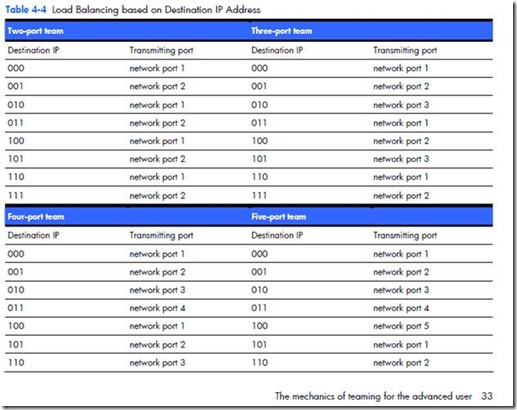
Because IP addresses are in decimal format, it is necessary to convert them to binary format. For example, an IP address of 1.2.3.4 (dotted decimal) would be 0000 0001.00000010.00000011.0000 0100 in binary format. The teaming driver only uses the last three bits (100) of the least significant byte (0000 0100 = 4) of the IP address. Utilizing these three bits, the teaming driver consecutively assigns destination IP addresses to each functional network port in its team starting with 000 being assigned to network port 1, 001 being assigned to network port 2, and so on. Of course, how the IP addresses are assigned depends on the number of network ports in the TLB team and how many of those ports are in a functional state (see Table 4-4).
3. How to configure 802.3ad with Cisco and HP Procurve?
3.1 Configuration of Cisco Switch with 2 network ports
Switch#conf ter
Switch(config)#Int PORT (a.e. Gi3/1)
Switch(config-if)#switchport mode access
Switch(config-if)#spanning-tree portfast
Switch(config-if)#channel-group <48> mode active
Switch(config-if)#Int PORT (a.e. Gi3/1)
Switch(config-if)#switchport mode access
Switch(config-if)#spanning-tree portfast
Switch(config-if)#channel-group <48> mode active
3.2 Configuration of HP Procurve with 2 network ports
PROCURVE-Core1#conf ter
PROCURVE-Core1# trunk PORT1-PORT2 (a.e. C1/C2) Trk<ID> (a.e. Trk99) LACP
PROCURVE-Core1# vlan <VLANID>
PROCURVE-Core1# untagged Trk<ID> (a.e. Trk99)
PROCURVE-Core1# show lacp
PROCURVE-Core1# show log lacp
a.e.: How to add additional ports to an existing HP trunk?
Note: In this example I do add port D5 and D6 to an configured trunk with trunk ID 70. In total I do have here an 4 port NIC team with ports C23, C24, D5, D6 based on LACP.
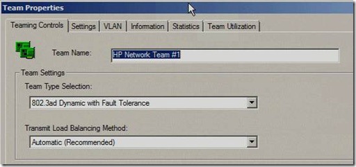
3.3 Configuration of HP NIC
NOTE: Automatic can also be used, as the teaming network drivers will automatically detect and handle the best teaming method with the switches => 802.3ad Dynamic Fault Tolerance
3.4 Results in “sh running-config” in Cisco Example
interface GigabitEthernet3/1
description SERVERNAME-NIC1
switchport access vlan <VLANID>
switchport mode access
spanning-tree portfast
channel-group 60 mode active
interface GigabitEthernet3/2
description SERVERNAME-NIC2
switchport access vlan <VLANID>
switchport mode access
spanning-tree portfast
channel-group <1-48> mode active
interface Port-channel<1-48>
description SERVERNAME-TEAM1
switchport
switchport access vlan <VLANID>
switchport mode access
3.5 Results in “sh int status” in Cisco Example
Gi3/1 SERVERNAME-NIC1 connected 10 a-full a-1000
Gi3/2 SERVERNAME-NIC2 connected 10 a-full a-1000
Po60 SERVERNAME-TEAM1 connected 10 a-full a-1000
Note: In this example the network ports Gi3/1 and Gi3/2 are bound to an new PortChannel (Po60) which is created and connected to VLAN10.
4. References
https://www.cisco.com/application/pdf/paws/98469/ios_etherchannel.pdf
https://cdn.procurve.com/training/Manuals/2900-MCG-Jan08-11-PortTrunk.pdf
IMPORTANTE: In NIC Teaming with HP hardware scenarios especially when Hyper-V is involved it is important to follow the installation guide from the NIC manufacturer, in case of HP NCU it is mainly important to strictly follow the installation order:
1. Install OS + patches
2. Install Hyper-V role
3. Install NCU (Network Configuration Utility) (included in Proliant Support Pack, current version 8.70)
More detailed steps can you find in the HP reference guide here:
Using HP ProLiant Network Teaming Software with Microsoft® Windows® Server 2008 (R2) Hyper-V (4th Edition)
https://h20000.www2.hp.com/bc/docs/support/SupportManual/c01663264/c01663264.pdf
Note: Please be aware most of this blog post are cross-references from HP and Cisco networking documentation.
Stay tuned …. ![]()
Regards
Ramazan
Comments
- Anonymous
August 09, 2011
Hi Ramazan,greate article exactly what I searched for.Regards Carstenhttp://www.hyper-v-server.de - Anonymous
August 18, 2011
fantastic article - Anonymous
January 12, 2012
Just curious if you know whether NFT with Preference order requires a port channel or not. We have it working without a port channel but I have a lack of confidence in the HP support representative who indicated such. He didn't sound extremely sure.- Anonymous
September 11, 2012
No NFT doesn't need an portchannel ;)
- Anonymous
- Anonymous
June 08, 2012
Reblogged this on notepad. - Anonymous
June 13, 2012
Thank you, this is helpful. - Anonymous
July 12, 2012
Great article, very useful. I based on it during configuration my HP switches to work tohether with HP Network Configuration Utility. Works great. - Anonymous
August 04, 2012
Great write up. When I tried to setup 802.3ad Dynamic, I found out my team needed to be part of a vlan and in Dynamic trunks the trunk defaults to the default vlan, a little harder to setup but was able to setup a static lacp trunk and use Dynamic teaming and it worked ok. - Anonymous
January 29, 2013
I had some doubts, after reading this post Used Cisco Switches. I am cleared now. Keep up the good work. This blog is really interesting and gives good details. - Anonymous
February 11, 2013
Excellent write up. If this is for one VLAN (10) in your example, would it be possible to setup this for 2 VLAN's?- Anonymous
March 18, 2013
yes it is, as we configured the port as a "Trunk Port" you can allow multimple VLANs.switchport trunk allowed vlan add 10,11more here -> https://supportforums.cisco.com/docs/DOC-2218
- Anonymous
- Anonymous
June 04, 2013
Extremely well documented. Imagine, this still runs as a top find in Google when searched. I understand why. Clear, succinct and worth the read Thank you for this... - Anonymous
April 25, 2014
Great article.. i would like to add, regarding VLAN config, that ( AFAIK ) at least 1 untagged VLAN is required on port where are connected the teamed NIC, because the heartbeat communication between team member seem to use untagged packet.


