Cenni preliminari sulla geometria
Questa panoramica descrive come usare le classi di windows Presentation Foundation (WPF) Geometry per descrivere le forme. In questo argomento vengono inoltre contrastete le differenze tra gli oggetti Geometry e gli elementi Shape.
Che cos'è una geometria?
La classe Geometry e le classi che ne derivano, ad esempio EllipseGeometry, PathGeometrye CombinedGeometry, consentono di descrivere la geometria di una forma 2D. Queste descrizioni geometriche hanno molti usi, ad esempio la definizione di una forma da disegnare sullo schermo o la definizione di aree di hit test e clip. Puoi anche usare una geometria per definire un percorso di animazione.
Geometry oggetti possono essere semplici, come rettangoli e cerchi, oppure composti, creati da due o più oggetti geometrici. È possibile creare geometrie più complesse usando le classi PathGeometry e StreamGeometry, che consentono di descrivere archi e curve.
Poiché un Geometry è un tipo di Freezable, gli oggetti Geometry forniscono diverse funzionalità speciali: possono essere dichiarate come risorse , condivise tra più oggetti, rese di sola lettura per migliorare le prestazioni, clonate e rese thread-safe. Per ulteriori informazioni sulle diverse funzionalità fornite dagli oggetti Freezable, vedere la Panoramica sugli Oggetti Freezable .
Geometrie e forme
Le classi Geometry e Shape sembrano simili in quanto descrivono entrambe le forme 2D (confrontare EllipseGeometry e Ellipse ad esempio), ma esistono differenze importanti.
Innanzitutto, la classe Geometry eredita dalla classe Freezable mentre la classe Shape eredita da FrameworkElement. Poiché sono elementi, gli oggetti Shape possono renderizzarsi e partecipare al sistema di layout, mentre gli oggetti Geometry non possono.
Anche se Shape oggetti sono più facilmente utilizzabili rispetto agli oggetti Geometry, gli oggetti Geometry sono più versatili. Mentre un oggetto Shape viene usato per eseguire il rendering della grafica 2D, un oggetto Geometry può essere usato per definire l'area geometrica per la grafica 2D, definire un'area per ritagliare o definire un'area per l'hit testing, ad esempio.
La Forma del Percorso
Una Shape, la classe Path, usa effettivamente un Geometry per descriverne il contenuto. Impostando la proprietà Data del Path con un Geometry e impostando le relative proprietà Fill e Stroke, è possibile eseguire il rendering di un Geometry.
Proprietà comuni che richiedono una geometria
Le sezioni precedenti hanno indicato che gli oggetti Geometry possono essere utilizzati con altri oggetti per diversi scopi, ad esempio disegnare forme, animare e ritagliare. Nella tabella seguente sono elencate diverse classi con proprietà che accettano un oggetto Geometry.
| Digitare | Proprietà |
|---|---|
| DoubleAnimationUsingPath | PathGeometry |
| DrawingGroup | ClipGeometry |
| GeometryDrawing | Geometry |
| Path | Data |
| UIElement | Clip |
Tipi di geometria semplici
La classe base per tutte le geometrie è la classe astratta Geometry. Le classi che derivano dalla classe Geometry possono essere raggruppate approssimativamente in tre categorie: geometrie semplici, geometrie di percorso e geometrie composite.
Le classi geometry semplici includono LineGeometry, RectangleGeometrye EllipseGeometry e vengono usate per creare forme geometriche di base, ad esempio linee, rettangoli e cerchi.
Un LineGeometry viene definito specificando il punto iniziale della riga e il punto finale.
Un RectangleGeometry viene definito con una struttura Rect che specifica la posizione relativa e l'altezza e la larghezza. È possibile creare un rettangolo arrotondato impostando le proprietà RadiusX e RadiusY.
Un EllipseGeometry è definito da un punto centrale, un raggio x e un raggio y. Negli esempi seguenti viene illustrato come creare geometrie semplici per il rendering e per il ritaglio.
Queste stesse forme, così come forme più complesse, possono essere create usando un PathGeometry o combinando oggetti geometrici, ma queste classi forniscono un mezzo più semplice per produrre queste forme geometriche di base.
Nell'esempio seguente viene illustrato come creare ed eseguire il rendering di un LineGeometry. Come indicato in precedenza, un oggetto Geometry non è in grado di disegnare se stesso, pertanto nell'esempio viene utilizzata una forma Path per eseguire il rendering della linea. Poiché una linea non ha alcuna area, l'impostazione della proprietà Fill del Path non avrà alcun effetto; Vengono invece specificate solo le proprietà Stroke e StrokeThickness. La figura seguente mostra l'output dell'esempio.
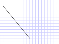
La LineGeometry disegnata da (10,20) a (100,130)
<Path Stroke="Black" StrokeThickness="1" >
  <Path.Data>
    <LineGeometry StartPoint="10,20" EndPoint="100,130" />
  </Path.Data>
</Path>
LineGeometry myLineGeometry = new LineGeometry();
myLineGeometry.StartPoint = new Point(10,20);
myLineGeometry.EndPoint = new Point(100,130);

Path myPath = new Path();
myPath.Stroke = Brushes.Black;
myPath.StrokeThickness = 1;
myPath.Data = myLineGeometry;
Dim myLineGeometry As New LineGeometry()
myLineGeometry.StartPoint = New Point(10,20)
myLineGeometry.EndPoint = New Point(100,130)

Dim myPath As New Path()
myPath.Stroke = Brushes.Black
myPath.StrokeThickness = 1
myPath.Data = myLineGeometry
Nell'esempio seguente viene illustrato come creare ed eseguire il rendering di un EllipseGeometry. Negli esempi viene impostata la Center del EllipseGeometry sul punto 50,50 e il raggio x e il raggio y sono entrambi impostati su 50, che crea un cerchio con un diametro pari a 100. L'interno dell'ellisse viene disegnato assegnando un valore alla proprietà Fill dell'elemento Path, in questo caso Gold. La figura seguente mostra l'output dell'esempio.
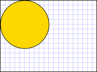
Un oggetto EllipseGeometry disegnato a (50,50)
<Path Fill="Gold" Stroke="Black" StrokeThickness="1">
  <Path.Data>
    <EllipseGeometry Center="50,50" RadiusX="50" RadiusY="50" />
  </Path.Data>
</Path>
EllipseGeometry myEllipseGeometry = new EllipseGeometry();
myEllipseGeometry.Center = new Point(50, 50);
myEllipseGeometry.RadiusX = 50;
myEllipseGeometry.RadiusY = 50;

Path myPath = new Path();
myPath.Fill = Brushes.Gold;
myPath.Stroke = Brushes.Black;
myPath.StrokeThickness = 1;
myPath.Data = myEllipseGeometry;
Dim myEllipseGeometry As New EllipseGeometry()
myEllipseGeometry.Center = New Point(50, 50)
myEllipseGeometry.RadiusX = 50
myEllipseGeometry.RadiusY = 50

Dim myPath As New Path()
myPath.Fill = Brushes.Gold
myPath.Stroke = Brushes.Black
myPath.StrokeThickness = 1
myPath.Data = myEllipseGeometry
Nell'esempio seguente viene illustrato come creare ed eseguire il rendering di un RectangleGeometry. La posizione e le dimensioni del rettangolo sono definite da una struttura Rect. La posizione è 50,50 e l'altezza e la larghezza sono entrambi 25, che crea un quadrato. La figura seguente mostra l'output dell'esempio.
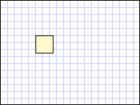
Oggetto RectangleGeometry disegnato a 50,50
<Path Fill="LemonChiffon" Stroke="Black" StrokeThickness="1">
  <Path.Data>
    <RectangleGeometry Rect="50,50,25,25" />
  </Path.Data>
</Path>
RectangleGeometry myRectangleGeometry = new RectangleGeometry();
myRectangleGeometry.Rect = new Rect(50,50,25,25);

Path myPath = new Path();
myPath.Fill = Brushes.LemonChiffon;
myPath.Stroke = Brushes.Black;
myPath.StrokeThickness = 1;
myPath.Data = myRectangleGeometry;
Dim myRectangleGeometry As New RectangleGeometry()
myRectangleGeometry.Rect = New Rect(50,50,25,25)

Dim myPath As New Path()
myPath.Fill = Brushes.LemonChiffon
myPath.Stroke = Brushes.Black
myPath.StrokeThickness = 1
myPath.Data = myRectangleGeometry
Nell'esempio seguente viene illustrato come usare un EllipseGeometry come area di ritaglio per un'immagine. Un oggetto Image viene definito con un Width di 200 e un Height di 150. Un EllipseGeometry con un valore RadiusX pari a 100, un valore RadiusY pari a 75 e un valore Center pari a 100.75 viene impostato sulla proprietà Clip dell'immagine. Verrà visualizzata solo la parte dell'immagine che si trova all'interno dell'area dell'ellisse. La figura seguente mostra l'output dell'esempio.
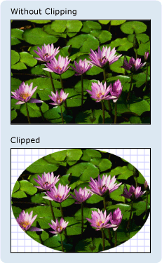
Oggetto EllipseGeometry utilizzato per ritagliare un controllo Immagine
<Image
  Source="sampleImages\Waterlilies.jpg"
  Width="200" Height="150" HorizontalAlignment="Left">
  <Image.Clip>
    <EllipseGeometry
      RadiusX="100"
      RadiusY="75"
      Center="100,75"/>
  </Image.Clip>
</Image>
// Create the image to clip.
Image myImage = new Image();
Uri imageUri =
    new Uri(@"C:\\Documents and Settings\\All Users\\Documents\My Pictures\\Sample Pictures\\Water lilies.jpg", UriKind.Relative);
myImage.Source = new BitmapImage(imageUri);
myImage.Width = 200;
myImage.Height = 150;
myImage.HorizontalAlignment = HorizontalAlignment.Left;

// Use an EllipseGeometry to define the clip region.
EllipseGeometry myEllipseGeometry = new EllipseGeometry();
myEllipseGeometry.Center = new Point(100, 75);
myEllipseGeometry.RadiusX = 100;
myEllipseGeometry.RadiusY = 75;
myImage.Clip = myEllipseGeometry;
' Create the image to clip.
Dim myImage As New Image()
Dim imageUri As New Uri("C:\\Documents and Settings\\All Users\\Documents\My Pictures\\Sample Pictures\\Water lilies.jpg", UriKind.Relative)
myImage.Source = New BitmapImage(imageUri)
myImage.Width = 200
myImage.Height = 150
myImage.HorizontalAlignment = HorizontalAlignment.Left

' Use an EllipseGeometry to define the clip region.
Dim myEllipseGeometry As New EllipseGeometry()
myEllipseGeometry.Center = New Point(100, 75)
myEllipseGeometry.RadiusX = 100
myEllipseGeometry.RadiusY = 75
myImage.Clip = myEllipseGeometry
Geometrie di percorso
La classe PathGeometry e l'equivalente leggero, la classe StreamGeometry, forniscono i mezzi per descrivere più figure complesse composte da archi, curve e linee.
Al centro di un PathGeometry è una raccolta di oggetti PathFigure, così denominata perché ogni figura descrive una forma discreta nel PathGeometry. Ogni PathFigure è costituita da uno o più oggetti PathSegment, ognuno dei quali descrive un segmento della figura.
Esistono molti tipi di segmenti.
| Tipo di segmento | Descrizione | Esempio |
|---|---|---|
| ArcSegment | Crea un arco ellittico tra due punti. | Creare un arco ellittico. |
| BezierSegment | Crea una curva di Bézier cubica tra due punti. | Creare una curva di Bézier cubica. |
| LineSegment | Crea una linea tra due punti. | Creare un segmento di linea in un PathGeometry |
| PolyBezierSegment | Crea una serie di curve di Bézier cubiche. | Vedi la pagina tipo PolyBezierSegment. |
| PolyLineSegment | Crea una serie di linee. | Vedere la pagina di tipo PolyLineSegment. |
| PolyQuadraticBezierSegment | Crea una serie di curve di Bézier quadratiche. | Consulta la pagina PolyQuadraticBezierSegment. |
| QuadraticBezierSegment | Crea una curva di Bézier quadratica. | Creare una curva quadratica di Bézier. |
I segmenti all'interno di un PathFigure vengono combinati in una singola forma geometrica con il punto finale di ogni segmento che rappresenta il punto iniziale del segmento successivo. La proprietà StartPoint di un PathFigure specifica il punto da cui viene disegnato il primo segmento. Ogni segmento successivo inizia al punto finale del segmento precedente. Ad esempio, una linea verticale da 10,50 a 10,150 può essere definita impostando la proprietà StartPoint su 10,50 e creando un LineSegment con un'impostazione della proprietà Point di 10,150.
Nell'esempio seguente viene creato un semplice PathGeometry costituito da un singolo PathFigure con un LineSegment, che viene visualizzato utilizzando un elemento Path. Il StartPoint dell'oggetto PathFigure è impostato su 10,20 e viene definito un LineSegment con un punto finale di 100,130. Nella figura seguente viene illustrato il PathGeometry creato da questo esempio.

Una PathGeometry che contiene un singolo LineSegment
<Path Stroke="Black" StrokeThickness="1">
  <Path.Data>
    <PathGeometry>
      <PathGeometry.Figures>
        <PathFigure StartPoint="10,20">
          <PathFigure.Segments>
            <LineSegment Point="100,130"/>
          </PathFigure.Segments>
        </PathFigure>
      </PathGeometry.Figures>
    </PathGeometry>
  </Path.Data>
</Path>
// Create a figure that describes a
// line from (10,20) to (100,130).
PathFigure myPathFigure = new PathFigure();
myPathFigure.StartPoint = new Point(10,20);
myPathFigure.Segments.Add(
    new LineSegment(new Point(100,130),
    true /* IsStroked */ ));

/// Create a PathGeometry to contain the figure.
PathGeometry myPathGeometry = new PathGeometry();
myPathGeometry.Figures.Add(myPathFigure);

// Display the PathGeometry.
Path myPath = new Path();
myPath.Stroke = Brushes.Black;
myPath.StrokeThickness = 1;
myPath.Data = myPathGeometry;
' Create a figure that describes a
' line from (10,20) to (100,130).
Dim myPathFigure As New PathFigure()
myPathFigure.StartPoint = New Point(10,20)
myPathFigure.Segments.Add(New LineSegment(New Point(100,130), True)) ' IsStroked

''' Create a PathGeometry to contain the figure.
Dim myPathGeometry As New PathGeometry()
myPathGeometry.Figures.Add(myPathFigure)

' Display the PathGeometry.
Dim myPath As New Path()
myPath.Stroke = Brushes.Black
myPath.StrokeThickness = 1
myPath.Data = myPathGeometry
Vale la pena confrontare questo esempio con l'esempio precedente LineGeometry. La sintassi usata per un PathGeometry è molto più dettagliata di quella usata per una semplice LineGeometrye potrebbe essere più logico usare la classe LineGeometry in questo caso, ma la sintassi dettagliata del PathGeometry consente regioni geometriche estremamente intricate e complesse.
È possibile creare geometrie più complesse usando una combinazione di oggetti PathSegment.
Nell'esempio seguente viene utilizzato un BezierSegment, un LineSegmente un ArcSegment per creare la forma. L'esempio crea prima una curva di Bézier cubica definendo quattro punti: un punto iniziale, ovvero il punto finale del segmento precedente, un punto finale (Point3) e due punti di controllo (Point1 e Point2). I due punti di controllo di una curva cubica di Bézier si comportano come magneti, attirando parti di ciò che altrimenti sarebbe una linea retta verso se stessi, producendo una curva. Il primo punto di controllo, Point1, influisce sulla parte iniziale della curva; il secondo punto di controllo, Point2, influisce sulla parte finale della curva.
Nell'esempio viene quindi aggiunto un LineSegment, che viene disegnato tra il punto finale del BezierSegment precedente e il punto specificato dalla proprietà LineSegment.
Nell'esempio viene quindi aggiunto un ArcSegment, che viene disegnato a partire dal punto finale del LineSegment precedente fino al punto specificato dalla sua proprietà Point. Nell'esempio viene inoltre specificato il raggio x e y dell'arco (Size), un angolo di rotazione (RotationAngle), un flag che indica la grandezza dell'angolo dell'arco risultante (IsLargeArc) e un valore che indica in quale direzione viene disegnato l'arco (SweepDirection). Nella figura seguente viene illustrata la forma creata da questo esempio.
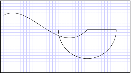
Una PathGeometry
<Path Stroke="Black" StrokeThickness="1" >
  <Path.Data>
    <PathGeometry>
      <PathGeometry.Figures>
        <PathFigure StartPoint="10,50">
          <PathFigure.Segments>
            <BezierSegment
              Point1="100,0"
              Point2="200,200"
              Point3="300,100"/>
            <LineSegment Point="400,100" />
            <ArcSegment
              Size="50,50" RotationAngle="45"
              IsLargeArc="True" SweepDirection="Clockwise"
              Point="200,100"/>
          </PathFigure.Segments>
        </PathFigure>
      </PathGeometry.Figures>
    </PathGeometry>
  </Path.Data>
</Path>
// Create a figure.
PathFigure myPathFigure = new PathFigure();
myPathFigure.StartPoint = new Point(10,50);
myPathFigure.Segments.Add(
    new BezierSegment(
        new Point(100,0),
        new Point(200,200),
        new Point(300,100),
        true /* IsStroked */  ));
myPathFigure.Segments.Add(
    new LineSegment(
        new Point(400,100),
        true /* IsStroked */ ));
myPathFigure.Segments.Add(
    new ArcSegment(
        new Point(200,100),
        new Size(50,50),
        45,
        true, /* IsLargeArc */
        SweepDirection.Clockwise,
        true /* IsStroked */ ));

/// Create a PathGeometry to contain the figure.
PathGeometry myPathGeometry = new PathGeometry();
myPathGeometry.Figures.Add(myPathFigure);

// Display the PathGeometry.
Path myPath = new Path();
myPath.Stroke = Brushes.Black;
myPath.StrokeThickness = 1;
myPath.Data = myPathGeometry;
' Create a figure.
Dim myPathFigure As New PathFigure()
myPathFigure.StartPoint = New Point(10,50)
myPathFigure.Segments.Add(New BezierSegment(New Point(100,0), New Point(200,200), New Point(300,100), True)) ' IsStroked
myPathFigure.Segments.Add(New LineSegment(New Point(400,100), True)) ' IsStroked
myPathFigure.Segments.Add(New ArcSegment(New Point(200,100), New Size(50,50), 45, True, SweepDirection.Clockwise, True)) ' IsStroked  -  IsLargeArc

''' Create a PathGeometry to contain the figure.
Dim myPathGeometry As New PathGeometry()
myPathGeometry.Figures.Add(myPathFigure)

' Display the PathGeometry.
Dim myPath As New Path()
myPath.Stroke = Brushes.Black
myPath.StrokeThickness = 1
myPath.Data = myPathGeometry
È possibile creare geometrie ancora più complesse usando più oggetti PathFigure all'interno di un PathGeometry.
Nell'esempio seguente viene creato un PathGeometry con due oggetti PathFigure, ognuno dei quali contiene più oggetti PathSegment. Vengono utilizzati il PathFigure dall'esempio precedente e un PathFigure con un PolyLineSegment e un QuadraticBezierSegment. Un PolyLineSegment viene definito con una matrice di punti e il QuadraticBezierSegment viene definito con un punto di controllo e un punto finale. Nella figura seguente viene illustrata la forma creata da questo esempio.
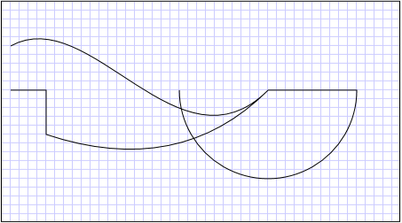
Una PathGeometry con più figure
<Path Stroke="Black" StrokeThickness="1" >
  <Path.Data>
    <PathGeometry>
      <PathGeometry.Figures>
        <PathFigure StartPoint="10,50">
          <PathFigure.Segments>
            <BezierSegment
              Point1="100,0"
              Point2="200,200"
              Point3="300,100"/>
            <LineSegment Point="400,100" />
            <ArcSegment
              Size="50,50" RotationAngle="45"
              IsLargeArc="True" SweepDirection="Clockwise"
              Point="200,100"/>
          </PathFigure.Segments>
        </PathFigure>

        <PathFigure StartPoint="10,100">
          <PathFigure.Segments>
            <PolyLineSegment Points="50,100 50,150" />
            <QuadraticBezierSegment Point1="200,200" Point2="300,100"/>
          </PathFigure.Segments>
        </PathFigure>
      </PathGeometry.Figures>
    </PathGeometry>
  </Path.Data>
</Path>
PathGeometry myPathGeometry = new PathGeometry();

// Create a figure.
PathFigure pathFigure1 = new PathFigure();
pathFigure1.StartPoint = new Point(10,50);
pathFigure1.Segments.Add(
    new BezierSegment(
        new Point(100,0),
        new Point(200,200),
        new Point(300,100),
        true /* IsStroked */ ));
pathFigure1.Segments.Add(
    new LineSegment(
        new Point(400,100),
        true /* IsStroked */ ));
pathFigure1.Segments.Add(
    new ArcSegment(
        new Point(200,100),
        new Size(50,50),
        45,
        true, /* IsLargeArc */
        SweepDirection.Clockwise,
        true /* IsStroked */ ));
myPathGeometry.Figures.Add(pathFigure1);

// Create another figure.
PathFigure pathFigure2 = new PathFigure();
pathFigure2.StartPoint = new Point(10,100);
Point[] polyLinePointArray =
    new Point[]{ new Point(50, 100), new Point(50, 150)};
PolyLineSegment myPolyLineSegment = new PolyLineSegment();
myPolyLineSegment.Points =
    new PointCollection(polyLinePointArray);
pathFigure2.Segments.Add(myPolyLineSegment);
pathFigure2.Segments.Add(
    new QuadraticBezierSegment(
        new Point(200,200),
        new Point(300,100),
        true /* IsStroked */ ));
myPathGeometry.Figures.Add(pathFigure2);

// Display the PathGeometry.
Path myPath = new Path();
myPath.Stroke = Brushes.Black;
myPath.StrokeThickness = 1;
myPath.Data = myPathGeometry;
Dim myPathGeometry As New PathGeometry()

' Create a figure.
Dim pathFigure1 As New PathFigure()
pathFigure1.StartPoint = New Point(10,50)
pathFigure1.Segments.Add(New BezierSegment(New Point(100,0), New Point(200,200), New Point(300,100), True)) ' IsStroked
pathFigure1.Segments.Add(New LineSegment(New Point(400,100), True)) ' IsStroked
pathFigure1.Segments.Add(New ArcSegment(New Point(200,100), New Size(50,50), 45, True, SweepDirection.Clockwise, True)) ' IsStroked  -  IsLargeArc
myPathGeometry.Figures.Add(pathFigure1)

' Create another figure.
Dim pathFigure2 As New PathFigure()
pathFigure2.StartPoint = New Point(10,100)
Dim polyLinePointArray() As Point = { New Point(50, 100), New Point(50, 150)}
Dim myPolyLineSegment As New PolyLineSegment()
myPolyLineSegment.Points = New PointCollection(polyLinePointArray)
pathFigure2.Segments.Add(myPolyLineSegment)
pathFigure2.Segments.Add(New QuadraticBezierSegment(New Point(200,200), New Point(300,100), True)) ' IsStroked
myPathGeometry.Figures.Add(pathFigure2)

' Display the PathGeometry.
Dim myPath As New Path()
myPath.Stroke = Brushes.Black
myPath.StrokeThickness = 1
myPath.Data = myPathGeometry
StreamGeometry
Analogamente alla classe PathGeometry, un StreamGeometry definisce una forma geometrica complessa che può contenere curve, archi e linee. A differenza di un PathGeometry, il contenuto di un StreamGeometry non supporta il data binding, l'animazione o la modifica. Usare un StreamGeometry quando è necessario descrivere una geometria complessa, ma non si desidera il carico aggiuntivo di supporto per data binding, animazione o modifica. A causa della sua efficienza, la classe StreamGeometry è una buona scelta per descrivere gli adornatori.
Per un esempio, vedere Creare una forma usando StreamGeometry.
Sintassi di markup del percorso
I tipi PathGeometry e StreamGeometry supportano una sintassi dell'attributo XAML (Extensible Application Markup Language) usando una serie speciale di comandi di spostamento e disegno. Per ulteriori informazioni, vedere Sintassi di Markup del Percorso .
Geometrie composite
È possibile creare oggetti geometrici compositi usando un GeometryGroup, un CombinedGeometryo chiamando il metodo statico GeometryCombine.
L'oggetto CombinedGeometry e il metodo Combine esegue un'operazione booleana per combinare l'area definita da due geometrie. Gli oggetti Geometry che non hanno area vengono eliminati. È possibile combinare solo due oggetti Geometry (anche se queste due geometrie possono essere geometrie composte).
La classe GeometryGroup crea una fusione degli oggetti Geometry che contiene senza unire le aree. È possibile aggiungere un numero qualsiasi di oggetti Geometry a un GeometryGroup. Per un esempio, vedere Creare una forma composita.
Poiché non eseguono un'operazione di combinazione, l'uso di oggetti GeometryGroup offre vantaggi in termini di prestazioni rispetto all'uso di oggetti CombinedGeometry o al metodo Combine.
Geometrie combinate
La sezione precedente ha menzionato l'oggetto CombinedGeometry e il metodo Combine combinano l'area definita dalle geometrie contenute. L'enumerazione GeometryCombineMode specifica la modalità di combinazione delle geometrie. I valori possibili per la proprietà GeometryCombineMode sono: Union, Intersect, Excludee Xor.
Nell'esempio seguente viene definita una CombinedGeometry con una modalità di combinazione Union. Sia Geometry1 che il Geometry2 sono definiti come cerchi dello stesso raggio, ma con centri scostati di 50.
<Path Stroke="Black" StrokeThickness="1" Fill="#CCCCFF">
  <Path.Data>

    <!-- Combines two geometries using the union combine mode. -->
    <CombinedGeometry GeometryCombineMode="Union">
      <CombinedGeometry.Geometry1>
        <EllipseGeometry RadiusX="50" RadiusY="50" Center="75,75" />
      </CombinedGeometry.Geometry1>
      <CombinedGeometry.Geometry2>
        <EllipseGeometry RadiusX="50" RadiusY="50" Center="125,75" />
      </CombinedGeometry.Geometry2>
    </CombinedGeometry>
  </Path.Data>
</Path>
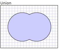
Nell'esempio seguente viene definito un CombinedGeometry con una modalità di combinazione di Xor. Sia Geometry1 che il Geometry2 sono definiti come cerchi dello stesso raggio, ma con centri scostati di 50.
<Path Stroke="Black" StrokeThickness="1" Fill="#CCCCFF">
  <Path.Data>

    <!-- Combines two geometries using the XOR combine mode. -->
    <CombinedGeometry GeometryCombineMode="Xor">
      <CombinedGeometry.Geometry1>
        <EllipseGeometry RadiusX="50" RadiusY="50" Center="75,75" />
      </CombinedGeometry.Geometry1>
      <CombinedGeometry.Geometry2>
        <EllipseGeometry RadiusX="50" RadiusY="50" Center="125,75" />
      </CombinedGeometry.Geometry2>
    </CombinedGeometry>
  </Path.Data>
</Path>
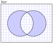
Per altri esempi, vedere Creare una forma composita e Creare una geometria combinata.
Funzionalità congelabili
Poiché eredita dalla classe Freezable, la classe Geometry fornisce diverse funzionalità speciali: gli oggetti Geometry possono essere dichiarati come risorse XAML , condivisi tra più oggetti, resi di sola lettura per migliorare le prestazioni, clonate e rese thread-safe. Per ulteriori informazioni sulle diverse caratteristiche fornite dagli oggetti Freezable, vedere Panorama sugli oggetti Freezable .
Altre funzionalità di geometria
La classe Geometry fornisce anche metodi di utilità utili, ad esempio i seguenti:
FillContains : determina se la geometria contiene un altro Geometry.
StrokeContains : determina se il tratto di un Geometry contiene un punto specificato.
Per un elenco completo dei relativi metodi, vedere la classe Geometry.
Vedere anche
.NET Desktop feedback
