Come disegnare e riempire una forma complessa
Direct2D fornisce l'interfaccia ID2D1PathGeometry per descrivere forme complesse che possono contenere curve, archi e linee. Questo argomento descrive come definire e eseguire il rendering di una geometria del percorso.
Per definire una geometria del percorso, usare prima il metodo ID2D1Factory::CreatePathGeometry per creare la geometria del percorso, quindi usare il metodo Open della geometria del percorso per recuperare un ID2D1GeometrySink. È quindi possibile aggiungere linee, curve e archi chiamando i vari metodi Add del sink.
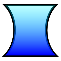
L'esempio seguente crea un ID2D1PathGeometry, recupera un sink e lo usa per definire una forma di clessidra.
ID2D1GeometrySink *pSink = NULL;

// Create a path geometry.
if (SUCCEEDED(hr))
{
    hr = m_pD2DFactory->CreatePathGeometry(&m_pPathGeometry);

    if (SUCCEEDED(hr))
    {
        // Write to the path geometry using the geometry sink.
        hr = m_pPathGeometry->Open(&pSink);

        if (SUCCEEDED(hr))
        {
            pSink->BeginFigure(
                D2D1::Point2F(0, 0),
                D2D1_FIGURE_BEGIN_FILLED
                );

            pSink->AddLine(D2D1::Point2F(200, 0));

            pSink->AddBezier(
                D2D1::BezierSegment(
                    D2D1::Point2F(150, 50),
                    D2D1::Point2F(150, 150),
                    D2D1::Point2F(200, 200))
                );

            pSink->AddLine(D2D1::Point2F(0, 200));

            pSink->AddBezier(
                D2D1::BezierSegment(
                    D2D1::Point2F(50, 150),
                    D2D1::Point2F(50, 50),
                    D2D1::Point2F(0, 0))
                );

            pSink->EndFigure(D2D1_FIGURE_END_CLOSED);

            hr = pSink->Close();
        }
        SafeRelease(&pSink);
    }
}
Si noti che un ID2D1PathGeometry è una risorsa indipendente dal dispositivo e può quindi essere creata una volta e mantenuta per la vita dell'applicazione. Per altre informazioni sui diversi tipi di risorse, vedere Panoramica delle risorse.
L'esempio successivo crea due pennelli che verranno usati per disegnare la struttura e il riempimento della geometria del percorso.
if (SUCCEEDED(hr))
{
    // Create a black brush.
    hr = m_pRenderTarget->CreateSolidColorBrush(
        D2D1::ColorF(D2D1::ColorF::Black),
        &m_pBlackBrush
        );
}

if (SUCCEEDED(hr))
{
    // Create a linear gradient.
    static const D2D1_GRADIENT_STOP stops[] =
    {
        {   0.f,  { 0.f, 1.f, 1.f, 0.25f }  },
        {   1.f,  { 0.f, 0.f, 1.f, 1.f }  },
    };

    hr = m_pRenderTarget->CreateGradientStopCollection(
        stops,
        ARRAYSIZE(stops),
        &pGradientStops
        );

    if (SUCCEEDED(hr))
    {
        hr = m_pRenderTarget->CreateLinearGradientBrush(
            D2D1::LinearGradientBrushProperties(
                D2D1::Point2F(100, 0),
                D2D1::Point2F(100, 200)),
            D2D1::BrushProperties(),
            pGradientStops,
            &m_pLGBrush
            );
    }

    SafeRelease(&pGradientStops);
}
L'esempio finale usa i metodi DrawGeometry e FillGeometry per disegnare la struttura e l'interno della geometria. In questo esempio viene generato l'output illustrato nella figura seguente.

void DemoApp::RenderGeometryExample()
{
    // Translate subsequent drawings by 20 device-independent pixels.
    m_pRenderTarget->SetTransform(
        D2D1::Matrix3x2F::Translation(20.f, 20.f)
        );

    // Draw the hour glass geometry at the upper left corner of the client area.
    m_pRenderTarget->DrawGeometry(m_pPathGeometry, m_pBlackBrush, 10.f);
    m_pRenderTarget->FillGeometry(m_pPathGeometry, m_pLGBrush);
}
Il codice è stato omesso da questo esempio. Per altre informazioni sulle geometrie, vedere Panoramica delle geometrie.