自訂效果
Direct2D 隨附一個效果程式庫,可執行各種常見的影像作業。 如需完整的效果清單,請參閱 內建效果 主題。 對於無法透過內建效果達成的功能,Direct2D 可讓您使用標準 HLSL撰寫自己的自訂效果。 您可以使用這些自訂效果以及隨附于 Direct2D 的內建效果。
若要查看完整的圖元、頂點和計算著色器效果範例,請參閱 D2DCustomEffects SDK 範例。
在本主題中,我們會示範設計和建立功能完整的自訂效果所需的步驟和概念。
簡介:效果內有哪些?
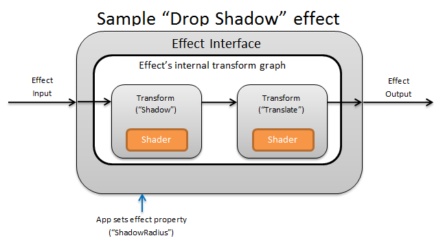
在概念上, Direct2D 效果會執行影像處理工作,例如變更亮度、解除飽和影像,或如上所示,建立陰影。 對應用程式,它們很簡單。 他們可以接受零或多個輸入影像、公開多個屬性來控制其作業,以及產生單一輸出影像。
效果作者負責的自訂效果有四個不同的部分:
- 效果介面:效果介面在概念上定義應用程式如何與自訂效果互動 (,例如效果所接受的輸入數目,以及可用的屬性) 。 效果介面會管理轉換圖形,其中包含實際的映射處理作業。
- 轉換圖表:每個效果都會建立由個別轉換組成的內部轉換圖形。 每個轉換都代表單一影像作業。 效果負責將這些轉換連結在一起,以執行預期的影像效果。 效果可以新增、移除、修改及重新排序轉換,以回應效果的外部屬性變更。
- 轉換:轉換代表單一影像作業。 其主要目的是要儲存針對每個輸出圖元執行的著色器。 為此,它會根據著色器中的邏輯,負責計算其輸出影像的新大小。 它也必須計算其輸入影像的哪個區域,著色器必須從中讀取,才能轉譯要求的輸出區域。
- 著色器:如果應用程式建立 Direct3D 裝置) 時,會針對 GPU 上的轉換輸入執行著色器 (或 CPU。 效果著色器是以高階網底語言 (HLSL) 撰寫,並在效果的編譯期間編譯成位元組程式碼,然後在執行時間由效果載入。 本參考檔說明如何撰寫 符合 Direct2D規範的 HLSL。 Direct3D 檔包含基本 HLSL 概觀。
建立效果介面
效果介面會定義應用程式如何與自訂效果互動。 若要建立效果介面,類別必須實作 ID2D1EffectImpl、定義描述效果的中繼資料 (,例如其名稱、輸入計數和屬性) ,以及建立註冊自訂效果以搭配 Direct2D使用的方法。
實作效果介面的所有元件之後,類別的標頭會顯示如下:
#include <d2d1_1.h>
#include <d2d1effectauthor.h>
#include <d2d1effecthelpers.h>

// Example GUID used to uniquely identify the effect. It is passed to Direct2D during
// effect registration, and used by the developer to identify the effect for any
// ID2D1DeviceContext::CreateEffect calls in the app. The app should create
// a unique name for the effect, as well as a unique GUID using a generation tool.
DEFINE_GUID(CLSID_SampleEffect, 0x00000000, 0x0000, 0x0000, 0x00, 0x00, 0x00, 0x00, 0x00, 0x00, 0x00, 0x00);

class SampleEffect : public ID2D1EffectImpl
{
public:
    // 2.1 Declare ID2D1EffectImpl implementation methods.
    IFACEMETHODIMP Initialize(
        _In_ ID2D1EffectContext* pContextInternal,
        _In_ ID2D1TransformGraph* pTransformGraph
        );

    IFACEMETHODIMP PrepareForRender(D2D1_CHANGE_TYPE changeType);
    IFACEMETHODIMP SetGraph(_In_ ID2D1TransformGraph* pGraph);

    // 2.2 Declare effect registration methods.
    static HRESULT Register(_In_ ID2D1Factory1* pFactory);
    static HRESULT CreateEffect(_Outptr_ IUnknown** ppEffectImpl);

    // 2.3 Declare IUnknown implementation methods.
    IFACEMETHODIMP_(ULONG) AddRef();
    IFACEMETHODIMP_(ULONG) Release();
    IFACEMETHODIMP QueryInterface(_In_ REFIID riid, _Outptr_ void** ppOutput);

private:
    // Constructor should be private since it should never be called externally.
    SampleEffect();

    LONG m_refCount; // Internal ref count used by AddRef() and Release() methods.
};
實作 ID2D1EffectImpl
ID2D1EffectImpl介面包含三種方法,您必須實作:
初始化 (ID2D1EffectCoNtext *pCoNtextInternal, ID2D1TransformGraph *pTransformGraph)
Direct2D會在應用程式呼叫ID2D1DeviceCoNtext::CreateEffect方法之後呼叫Initialize方法。 您可以使用這個方法來執行內部初始化,或效果所需的任何其他作業。 此外,您可以使用它來建立效果的初始轉換圖表。
SetGraph (ID2D1TransformGraph *pTransformGraph)
Direct2D 會在變更效果的輸入數目時呼叫 SetGraph 方法。 雖然大部分的效果都有固定數目的輸入,但 複合效果 等其他效果則支援可變數目的輸入。 此方法可讓這些效果更新其轉換圖表,以回應變更的輸入計數。 如果效果不支援變數輸入計數,這個方法可以直接傳回E_NOTIMPL。
PrepareForRender (D2D1_CHANGE_TYPE changeType)
PrepareForRender方法提供效果的機會,以執行任何作業以回應外部變更。 如果其中至少一個是 true,Direct2D會在它轉譯效果之前呼叫此方法:
- 效果先前已初始化,但尚未繪製。
- 效果屬性自上次繪製呼叫以來已變更。
- 呼叫 Direct2D 內容的狀態 (,例如 DPI) 自上次繪製呼叫以來已變更。
實作效果註冊和回呼方法
應用程式必須先向 Direct2D 註冊效果,才能具現化效果。 此註冊的範圍設定為 Direct2D 處理站的實例,而且每次執行應用程式時都必須重複。 若要啟用此註冊,自訂效果會定義唯一的 GUID、註冊效果的公用方法,以及傳回效果實例的私人回呼方法。
定義 GUID
您必須定義可唯一識別 Direct2D註冊效果的 GUID。 當應用程式呼叫 ID2D1DeviceCoNtext::CreateEffect時,會使用相同的來識別效果。
此程式碼示範如何定義效果的這類 GUID。 您必須使用 GUID 產生工具建立自己的唯一 GUID,例如 guidgen.exe。
// Example GUID used to uniquely identify the effect. It is passed to Direct2D during
// effect registration, and used by the developer to identify the effect for any
// ID2D1DeviceContext::CreateEffect calls in the app. The app should create
// a unique name for the effect, as well as a unique GUID using a generation tool.
DEFINE_GUID(CLSID_SampleEffect, 0x00000000, 0x0000, 0x0000, 0x00, 0x00, 0x00, 0x00, 0x00, 0x00, 0x00, 0x00);
定義公用註冊方法
接下來,為應用程式定義公用方法,以向 Direct2D註冊效果。 因為效果註冊是 Direct2D 處理站實例特有的,所以方法接受 ID2D1Factory1 介面做為參數。 若要註冊效果,方法接著會在ID2D1Factory1參數上呼叫ID2D1Factory1::RegisterEffectFromString API。
此 API 接受 XML 字串,描述效果的中繼資料、輸入和屬性。 效果的中繼資料僅供參考之用,且可由應用程式透過 ID2D1Properties 介面查詢。 另一方面, Direct2D 會使用輸入和屬性資料,並代表效果的功能。
此處會顯示最小樣本效果的 XML 字串。 將自訂屬性新增至 XML 涵蓋于將自訂屬性新增至效果區段。
#define XML(X) TEXT(#X) // This macro creates a single string from multiple lines of text.

PCWSTR pszXml =
    XML(
        <?xml version='1.0'?>
        <Effect>
            <!-- System Properties -->
            <Property name='DisplayName' type='string' value='SampleEffect'/>
            <Property name='Author' type='string' value='Contoso'/>
            <Property name='Category' type='string' value='Sample'/>
            <Property name='Description' type='string' value='This is a demo effect.'/>
            <Inputs>
                <Input name='SourceOne'/>
                <!-- <Input name='SourceTwo'/> -->
                <!-- Additional inputs go here. -->
            </Inputs>
            <!-- Custom Properties go here. -->
        </Effect>
        );
定義效果處理站回呼方法
效果也必須提供私用回呼方法,以透過單一 IUnknown** 參數傳回效果的實例。 當效果透過ID2D1Factory1::RegisterEffectFromString API 透過PD2D1_EFFECT_FACTORY\ 參數註冊效果時,會提供這個方法的指標。
HRESULT __stdcall SampleEffect::CreateEffect(_Outptr_ IUnknown** ppEffectImpl)
{
    // This code assumes that the effect class initializes its reference count to 1.
    *ppEffectImpl = static_cast<ID2D1EffectImpl*>(new SampleEffect());

    if (*ppEffectImpl == nullptr)
    {
        return E_OUTOFMEMORY;
    }

    return S_OK;
}
實作 IUnknown 介面
最後,效果必須實作 IUnknown 介面,才能與 COM 相容。
建立效果的轉換圖表
效果可以使用數個不同的轉換 (個別影像作業,) 建立其所需的影像效果。 若要控制這些轉換套用至輸入影像的順序,效果會將這些轉換排列成轉換圖形。 轉換圖表可以使用 Direct2D 中包含的效果和轉換,以及效果作者所建立的自訂轉換。
使用 Direct2D 隨附的轉換
這些是 Direct2D提供的最常見轉換。
- ID2D1BlendTransform:此轉換會根據混合描述將任意數目的輸入混合在一起,請參閱 D2D1_BLEND_DESCRIPTION 主題和混合 範例的 Direct2D 複合效果模式範例 。 此轉換是由 ID2D1EffectCoNtext::CreateBlendTransform 方法傳回。
- ID2D1BorderTransform:此轉換會根據指定的 D2D1_EXTEND_MODE 展開影像的輸出大小。 此轉換是由 ID2D1EffectCoNtext::CreateBorderTransform 方法傳回。
- ID2D1OffsetTransform:此轉換會位移 (以任何整數圖元轉譯其輸入) 。 此轉換是由 ID2D1EffectCoNtext::CreateOffsetTransform 方法傳回。
- 您可以使用 ID2D1EffectCoNtext::CreateTransformNodeFromEffect 方法,將任何現有的效果視為轉換圖形建立目的。
建立單一節點轉換圖表
建立轉換之後,效果的輸入必須連接到轉換的輸入,而轉換的輸出必須連接到效果的輸出。 當效果只包含單一轉換時,您可以使用 ID2D1TransformGraph::SetSingleTransformNode 方法輕鬆地完成這項作業。
您可以使用提供的 ID2D1TransformGraph 參數,在效果的 Initialize 或 SetGraph 方法中建立或修改轉換。 如果效果需要在無法使用此參數的另一個方法中變更轉換圖表,則效果可以將 ID2D1TransformGraph 參數儲存為類別的成員變數,並在其他地方存取,例如 PrepareForRender 或自訂屬性回呼方法。
範例 Initialize 方法如下所示。 這個方法會建立單一節點的轉換圖表,以在每個座標軸中將影像位移一百圖元。
IFACEMETHODIMP SampleEffect::Initialize(
    _In_ ID2D1EffectContext* pEffectContext,
    _In_ ID2D1TransformGraph* pTransformGraph
    )
{
    HRESULT hr = pEffectContext->CreateOffsetTransform(
        D2D1::Point2L(100,100),  // Offsets the input by 100px in each axis.
        &m_pOffsetTransform
        );

    if (SUCCEEDED(hr))
    {
        // Connects the effect's input to the transform's input, and connects
        // the transform's output to the effect's output.
        hr = pTransformGraph->SetSingleTransformNode(m_pOffsetTransform);
    }

    return hr;
}
建立多節點轉換圖表
將多個轉換新增至效果的轉換圖形,可讓效果在內部執行多個影像作業,以單一統一效果呈現給應用程式。
如上所述,效果的轉換圖形可以在任何效果方法中使用在效果的Initialize方法中收到的ID2D1TransformGraph參數進行編輯。 該介面上的下列 API 可用來建立或修改效果的轉換圖形:
AddNode (ID2D1TransformNode *pNode)
AddNode方法實際上會以效果'registers' 轉換,而且必須先呼叫,才能將轉換與任何其他轉換圖形方法搭配使用。
ConnectToEffectInput (UINT32 toEffectInputIndex, ID2D1TransformNode *pNode, UINT32 toNodeInputIndex)
ConnectToEffectInput方法會將效果的影像輸入連接到轉換的輸入。 相同的效果輸入可以連接到多個轉換。
ConnectNode (ID2D1TransformNode *pFromNode, ID2D1TransformNode *pToNode, UINT32 toNodeInputIndex)
ConnectNode方法會將轉換的輸出連接到另一個轉換的輸入。 轉換輸出可以連接到多個轉換。
SetOutputNode (ID2D1TransformNode *pNode)
SetOutputNode方法會將轉換的輸出連接到效果的輸出。 因為效果只有一個輸出,所以只能將單一轉換指定為「輸出節點」。
此程式碼會使用兩個不同的轉換來建立統一效果。 在此情況下,效果是轉譯的陰影。
IFACEMETHODIMP SampleEffect::Initialize(
    _In_ ID2D1EffectContext* pEffectContext,
    _In_ ID2D1TransformGraph* pTransformGraph
    )
{
    // Create the shadow effect.
    HRESULT hr = pEffectContext->CreateEffect(CLSID_D2D1Shadow, &m_pShadowEffect);

    // Create the shadow transform from the shadow effect.
    if (SUCCEEDED(hr))
    {
        hr = pEffectContext->CreateTransformNodeFromEffect(m_pShadowEffect, &m_pShadowTransform);
    }

    // Create the offset transform.
    if (SUCCEEDED(hr))
    {
        hr = pEffectContext->CreateOffsetTransform(
            D2D1::Point2L(0,0),
            &m_pOffsetTransform
            );
    }

    // Register both transforms with the effect graph.
    if (SUCCEEDED(hr))
    {
        hr = pTransformGraph->AddNode(m_pShadowTransform);
    }

    if (SUCCEEDED(hr))
    {
        hr = pTransformGraph->AddNode(m_pOffsetTransform);
    }

    // Connect the custom effect's input to the shadow transform's input.
    if (SUCCEEDED(hr))
    {
        hr = pTransformGraph->ConnectToEffectInput(
            0,                  // Input index of the effect.
            m_pShadowTransform, // The receiving transform.
            0                   // Input index of the receiving transform.
            );
    }

    // Connect the shadow transform's output to the offset transform's input.
    if (SUCCEEDED(hr))
    {
        hr = pTransformGraph->ConnectNode(
            m_pShadowTransform, // 'From' node.
            m_pOffsetTransform, // 'To' node.
            0                   // Input index of the 'to' node. There is only one output for the 'From' node.
            );
    }

    // Connect the offset transform's output to the custom effect's output.
    if (SUCCEEDED(hr))
    {
        hr = pTransformGraph->SetOutputNode(
            m_pOffsetTransform
            );
    }

    return hr;
}
將自訂屬性新增至效果
效果可以定義自訂屬性,讓應用程式在執行時間期間變更效果的行為。 定義自訂效果的屬性有三個步驟:
將屬性中繼資料新增至效果的註冊資料
將屬性新增至註冊 XML
您必須在效果的初始註冊與 Direct2D期間定義自訂效果的屬性。 首先,您必須使用新的 屬性,在其公用註冊方法中更新效果的註冊 XML:
PCWSTR pszXml =
    TEXT(
        <?xml version='1.0'?>
        <Effect>
            <!-- System Properties -->
            <Property name='DisplayName' type='string' value='SampleEffect'/>
            <Property name='Author' type='string' value='Contoso'/>
            <Property name='Category' type='string' value='Sample'/>
            <Property name='Description'
                type='string'
                value='Translates an image by a user-specifiable amount.'/>
            <Inputs>
                <Input name='Source'/>
                <!-- Additional inputs go here. -->
            </Inputs>
            <!-- Custom Properties go here. -->
            <Property name='Offset' type='vector2'>
                <Property name='DisplayName' type='string' value='Image Offset'/>
                <!— Optional sub-properties -->
                <Property name='Min' type='vector2' value='(-1000.0, -1000.0)' />
                <Property name='Max' type='vector2' value='(1000.0, 1000.0)' />
                <Property name='Default' type='vector2' value='(0.0, 0.0)' />
            </Property>
        </Effect>
        );
當您在 XML 中定義效果屬性時,它需要名稱、類型和顯示名稱。 屬性的顯示名稱,以及整體效果的類別、作者和描述值可以且應該當地語系化。
針對每個屬性,效果可以選擇性地指定預設值、最小值和最大值。 這些值僅供參考使用。 Direct2D不會強制執行它們。 您必須自行在效果類別中實作任何指定的 default/min/max 邏輯。
屬性的 XML 中列出的類型值必須符合屬性的 getter 和 setter 方法所使用的對應資料類型。 下表顯示每個資料類型的對應 XML 值:
| 資料類型 | 對應的 XML 值 |
|---|---|
| PWSTR | string |
| BOOL | bool |
| UINT | uint32 |
| INT | int32 |
| FLOAT | float |
| D2D_VECTOR_2F | vector2 |
| D2D_VECTOR_3F | vector3 |
| D2D_VECTOR_4F | vector4 |
| D2D_MATRIX_3X2_F | matrix3x2 |
| D2D_MATRIX_4X3_F | matrix4x3 |
| D2D_MATRIX_4X4_F | matrix4x4 |
| D2D_MATRIX_5X4_F | matrix5x4 |
| BYTE[] | blob |
| IUnknown* | iunknown |
| ID2D1ColorCoNtext* | colorcoNtext |
| CLSID | clsid |
| 列舉 (D2D1_INTERPOLATION_MODE等 ) | 列舉 |
將新屬性對應至 getter 和 setter 方法
接下來,效果必須將這個新屬性對應至 getter 和 setter 方法。 這是透過傳遞至ID2D1Factory1::RegisterEffectFromString方法的 D2D1_PROPERTY_BINDING陣列來完成。
D2D1_PROPERTY_BINDING陣列看起來像這樣:
const D2D1_PROPERTY_BINDING bindings[] =
{
    D2D1_VALUE_TYPE_BINDING(
        L"Offset",      // The name of property. Must match name attribute in XML.
        &SetOffset,     // The setter method that is called on "SetValue".
        &GetOffset      // The getter method that is called on "GetValue".
        )
};
建立 XML 和系結陣列之後,請將它們傳遞至 RegisterEffectFromString 方法:
pFactory->RegisterEffectFromString(
    CLSID_SampleEffect,  // GUID defined in class header file.
    pszXml,              // Previously-defined XML that describes effect.
    bindings,            // The previously-defined property bindings array.
    ARRAYSIZE(bindings), // Number of entries in the property bindings array.
    CreateEffect         // Static method that returns an instance of the effect's class.
    );
D2D1_VALUE_TYPE_BINDING宏需要效果類別在任何其他介面之前繼承自 ID2D1EffectImpl 。
效果的自訂屬性會依照在 XML 中宣告的順序編制索引,一旦建立之後,應用程式可以使用 ID2D1Properties::SetValue 和 ID2D1Properties::GetValue 方法來存取。 為了方便起見,您可以建立公用列舉,以列出效果標頭檔中的每個屬性:
typedef enum SAMPLEEFFECT_PROP
{
    SAMPLEFFECT_PROP_OFFSET = 0
};
建立 屬性的 getter 和 setter 方法
下一個步驟是建立新屬性的 getter 和 setter 方法。 方法的名稱必須符合 D2D1_PROPERTY_BINDING 陣列中指定的名稱。 此外,效果 XML 中指定的屬性類型必須符合 setter 方法的參數類型,以及 getter 方法的傳回值。
HRESULT SampleEffect::SetOffset(D2D_VECTOR_2F offset)
{
    // Method must manually clamp to values defined in XML.
    offset.x = min(offset.x, 1000.0f);
    offset.x = max(offset.x, -1000.0f);

    offset.y = min(offset.y, 1000.0f);
    offset.y = max(offset.y, -1000.0f);

    m_offset = offset;

    return S_OK;
}

D2D_VECTOR_2F SampleEffect::GetOffset() const
{
    return m_offset;
}
更新效果的轉換以回應屬性變更
若要實際更新效果的影像輸出以回應屬性變更,效果必須變更其基礎轉換。 這通常是在效果的 PrepareForRender 方法中完成,當其中一個效果的屬性變更時 ,Direct2D 會自動呼叫此方法。 不過,轉換可以在任何效果的 方法中更新:例如 Initialize 或效果的屬性 setter 方法。
例如,如果效果包含 ID2D1OffsetTransform ,而且想要修改其位移值以回應正在變更效果的 Offset 屬性,它會在 PrepareForRender中新增下列程式碼:
IFACEMETHODIMP SampleEffect::PrepareForRender(D2D1_CHANGE_TYPE changeType)
{
    // All effect properties are DPI independent (specified in DIPs). In this offset
    // example, the offset value provided must be scaled from DIPs to pixels to ensure
    // a consistent appearance at different DPIs (excluding minor scaling artifacts).
    // A context's DPI can be retrieved using the ID2D1EffectContext::GetDPI API.

    D2D1_POINT_2L pixelOffset;
    pixelOffset.x = static_cast<LONG>(m_offset.x * (m_dpiX / 96.0f));
    pixelOffset.y = static_cast<LONG>(m_offset.y * (m_dpiY / 96.0f));

    // Update the effect's offset transform with the new offset value.
    m_pOffsetTransform->SetOffset(pixelOffset);

    return S_OK;
}
建立自訂轉換
若要實作 Direct2D中所提供的映射作業,您必須實作自訂轉換。 自訂轉換可以透過使用自訂 HLSL 著色器來任意變更輸入影像。
轉換會根據所使用的著色器類型,實作兩個不同的介面之一。 使用圖元和/或頂點著色器的轉換必須實作 ID2D1DrawTransform,而使用計算著色器的轉換必須實作 ID2D1ComputeTransform。 這些介面都繼承自 ID2D1Transform。 本節著重于實作兩者通用的功能。
ID2D1Transform介面有四種方法可實作:
GetInputCount
這個方法會傳回整數,代表轉換的輸入計數。
IFACEMETHODIMP_(UINT32) GetInputCount() const
{
    return 1;
}
MapInputRectsToOutputRect
Direct2D 會在每次轉譯轉換時呼叫 MapInputRectsToOutputRect 方法。 Direct2D 會傳遞一個矩形,代表每個輸入到轉換的界限。 然後,轉換會負責計算輸出影像的界限。 此介面上所有方法的矩形大小 (ID2D1Transform) 是以圖元定義,而不是以 DIP 定義。
這個方法也負責根據其著色器的邏輯和每個輸入的不透明區域,計算輸出的區域。 影像的不透明區域定義為整個矩形的 Alpha 色板為 '1'。 如果不清楚轉換的輸出是否不透明,則輸出不透明矩形應該設定為 (0、0、0、0、0) 作為安全值。 Direct2D 會使用此資訊來執行具有「保證不透明」內容的轉譯優化。 如果此值不正確,可能會導致轉譯不正確。
您可以在此方法期間修改轉換的轉譯行為 (,如第 6 節到第) 8 節中所定義。 不過,您無法修改轉換圖形中的其他轉換,或在這裡修改圖形版面配置本身。
IFACEMETHODIMP SampleTransform::MapInputRectsToOutputRect(
    _In_reads_(inputRectCount) const D2D1_RECT_L* pInputRects,
    _In_reads_(inputRectCount) const D2D1_RECT_L* pInputOpaqueSubRects,
    UINT32 inputRectCount,
    _Out_ D2D1_RECT_L* pOutputRect,
    _Out_ D2D1_RECT_L* pOutputOpaqueSubRect
    )
{
    // This transform is designed to only accept one input.
    if (inputRectCount != 1)
    {
        return E_INVALIDARG;
    }

    // The output of the transform will be the same size as the input.
    *pOutputRect = pInputRects[0];
    // Indicate that the image's opacity has not changed.
    *pOutputOpaqueSubRect = pInputOpaqueSubRects[0];
    // The size of the input image can be saved here for subsequent operations.
    m_inputRect = pInputRects[0];

    return S_OK;
}
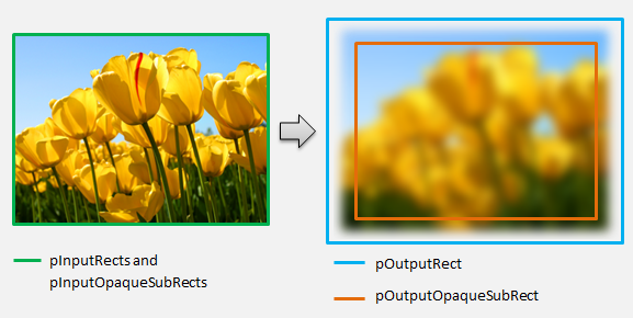
如需更複雜的範例,請考慮如何呈現簡單的模糊作業:
如果模糊作業使用 5 圖元半徑,輸出矩形的大小必須展開 5 圖元,如下所示。 修改矩形座標時,轉換必須確定其邏輯不會在矩形座標中造成任何過度/下溢。
// Expand output image by 5 pixels.

// Do not expand empty input rectangles.
if (pInputRects[0].right  > pInputRects[0].left &&
    pInputRects[0].bottom > pInputRects[0].top
    )
{
    pOutputRect->left   = ((pInputRects[0].left   - 5) < pInputRects[0].left  ) ? (pInputRects[0].left   - 5) : LONG_MIN;
    pOutputRect->top    = ((pInputRects[0].top    - 5) < pInputRects[0].top   ) ? (pInputRects[0].top    - 5) : LONG_MIN;
    pOutputRect->right  = ((pInputRects[0].right  + 5) > pInputRects[0].right ) ? (pInputRects[0].right  + 5) : LONG_MAX;
    pOutputRect->bottom = ((pInputRects[0].bottom + 5) > pInputRects[0].bottom) ? (pInputRects[0].bottom + 5) : LONG_MAX;
}
因為影像模糊,所以不透明影像的區域現在可能部分透明。 這是因為影像外部的區域預設為透明黑色,而且此透明度會混合到邊緣周圍的影像中。 轉換必須反映在其輸出不透明矩形計算中:
// Shrink opaque region by 5 pixels.
pOutputOpaqueSubRect->left   = pInputOpaqueSubRects[0].left   + 5;
pOutputOpaqueSubRect->top    = pInputOpaqueSubRects[0].top    + 5;
pOutputOpaqueSubRect->right  = pInputOpaqueSubRects[0].right  - 5;
pOutputOpaqueSubRect->bottom = pInputOpaqueSubRects[0].bottom - 5;
這些計算會在這裡視覺化:
如需這個方法的詳細資訊,請參閱 MapInputRectsToOutputRect 參考頁面。
MapOutputRectToInputRects
Direct2D會在MapInputRectsToOutputRectsToOutputRect 之後呼叫 MapOutputRectToInputRects方法。 轉換必須計算需要從中讀取的影像部分,才能正確轉譯要求的輸出區域。
如同之前,如果效果嚴格地對應圖元 1-1,它可以將輸出矩形傳遞至輸入矩形:
IFACEMETHODIMP SampleTransform::MapOutputRectToInputRects(
    _In_ const D2D1_RECT_L* pOutputRect,
    _Out_writes_(inputRectCount) D2D1_RECT_L* pInputRects,
    UINT32 inputRectCount
    ) const
{
    // This transform is designed to only accept one input.
    if (inputRectCount != 1)
    {
        return E_INVALIDARG;
    }

    // The input needed for the transform is the same as the visible output.
    pInputRects[0] = *pOutputRect;
    return S_OK;
}
同樣地,如果轉換縮小或展開影像 (像此處的模糊範例) ,圖元通常會使用周圍圖元來計算其值。 使用模糊時,即使圖元超出輸入影像的界限,圖元也會以其周圍圖元來平均。 此行為會反映在計算中。 如同之前,轉換會在展開矩形的座標時檢查溢位。
// Expand the input rectangle to reflect that more pixels need to
// be read from than are necessarily rendered in the effect's output.
pInputRects[0].left   = ((pOutputRect->left   - 5) < pOutputRect->left  ) ? (pOutputRect->left   - 5) : LONG_MIN;
pInputRects[0].top    = ((pOutputRect->top    - 5) < pOutputRect->top   ) ? (pOutputRect->top    - 5) : LONG_MIN;
pInputRects[0].right  = ((pOutputRect->right  + 5) > pOutputRect->right ) ? (pOutputRect->right  + 5) : LONG_MAX;
pInputRects[0].bottom = ((pOutputRect->bottom + 5) > pOutputRect->bottom) ? (pOutputRect->bottom + 5) : LONG_MAX;
此圖會將計算視覺化。 Direct2D 會自動取樣輸入影像不存在的透明黑色圖元,讓模糊逐漸與螢幕上的現有內容混合。
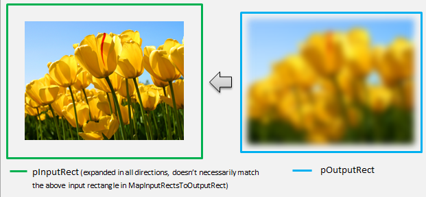
如果對應不是簡單的,則此方法應該將輸入矩形設定為最大區域,以確保正確的結果。 若要這樣做,請將左邊緣和上邊緣設定為 INT_MIN,並將右邊緣和下邊緣設定為 INT_MAX。
如需這個方法的詳細資訊,請參閱 MapOutputRectToInputRects 主題。
MapInvalidRect
Direct2D 也會呼叫 MapInvalidRect 方法。 不過,與 MapInputRectsToOutputRect 和 MapOutputRectToInputRects 方法不同,Direct2D 不保證在任何特定時間呼叫它。 此方法在概念上決定轉換輸出的哪個部分需要重新轉譯,以回應部分或所有輸入變更。 有三種不同的案例可計算轉換不正確 rect。
使用一對一圖元對應的轉換
對於對應圖元 1-1 的轉換,只要將不正確輸入矩形傳遞至不正確輸出矩形:
IFACEMETHODIMP SampleTransform::MapInvalidRect(
    UINT32 inputIndex,
    D2D1_RECT_L invalidInputRect,
    _Out_ D2D1_RECT_L* pInvalidOutputRect
    ) const
{
    // This transform is designed to only accept one input.
    if (inputIndex != 0)
    {
        return E_INVALIDARG;
    }

    // If part of the transform's input is invalid, mark the corresponding
    // output region as invalid.
    *pInvalidOutputRect = invalidInputRect;

    return S_OK;
}
具有多對多圖元對應的轉換
當轉換的輸出圖元相依于其周圍區域時,必須對應地展開不正確輸入矩形。 這是為了反映無效輸入矩形周圍的圖元也會受到影響,並變成無效。 例如,五個圖元模糊會使用下列計算:
// Expand the input invalid rectangle by five pixels in each direction. This
// reflects that a change in part of the given input image will cause a change
// in an expanded part of the output image (five pixels in each direction).
pInvalidOutputRect->left   = ((invalidInputRect.left   - 5) < invalidInputRect.left  ) ? (invalidInputRect.left   - 5) : LONG_MIN;
pInvalidOutputRect->top    = ((invalidInputRect.top    - 5) < invalidInputRect.top   ) ? (invalidInputRect.top    - 5) : LONG_MIN;
pInvalidOutputRect->right  = ((invalidInputRect.right  + 5) > invalidInputRect.right ) ? (invalidInputRect.right  + 5) : LONG_MAX;
pInvalidOutputRect->bottom = ((invalidInputRect.bottom + 5) > invalidInputRect.bottom) ? (invalidInputRect.bottom + 5) : LONG_MAX;
具有複雜圖元對應的轉換
對於輸入和輸出圖元沒有簡單對應的轉換,可以將整個輸出標示為無效。 例如,如果轉換只會輸出輸入的平均色彩,即使輸入的一小部分變更,轉換的整個輸出也會變更。 在此情況下,不正確輸出矩形應該設定為邏輯無限矩形, (如下所示) 。 Direct2D 會自動將此限制在輸出的界限。
// If any change in the input image affects the entire output, the
// transform should set pInvalidOutputRect to a logically infinite rect.
*pInvalidOutputRect = D2D1::RectL(LONG_MIN, LONG_MIN, LONG_MAX, LONG_MAX);
如需這個方法的詳細資訊,請參閱 MapInvalidRect 主題。
一旦實作這些方法,轉換的標頭將會包含下列內容:
class SampleTransform : public ID2D1Transform
{
public:
    SampleTransform();

    // ID2D1TransformNode Methods:
    IFACEMETHODIMP_(UINT32) GetInputCount() const;

    // ID2D1Transform Methods:
    IFACEMETHODIMP MapInputRectsToOutputRect(
        _In_reads_(inputRectCount) const D2D1_RECT_L* pInputRects,
        _In_reads_(inputRectCount) const D2D1_RECT_L* pInputOpaqueSubRects,
        UINT32 inputRectCount,
        _Out_ D2D1_RECT_L* pOutputRect,
        _Out_ D2D1_RECT_L* pOutputOpaqueSubRect
        );

    IFACEMETHODIMP MapOutputRectToInputRects(
        _In_ const D2D1_RECT_L* pOutputRect,
        _Out_writes_(inputRectCount) D2D1_RECT_L* pInputRects,
        UINT32 inputRectCount
        ) const;

    IFACEMETHODIMP MapInvalidRect(
        UINT32 inputIndex,
        D2D1_RECT_L invalidInputRect,
        _Out_ D2D1_RECT_L* pInvalidOutputRect
        ) const;

    // IUnknown Methods:
    IFACEMETHODIMP_(ULONG) AddRef();
    IFACEMETHODIMP_(ULONG) Release();
    IFACEMETHODIMP QueryInterface(REFIID riid, _Outptr_ void** ppOutput);

private:
    LONG m_cRef; // Internal ref count used by AddRef() and Release() methods.
    D2D1_RECT_L m_inputRect; // Stores the size of the input image.
};
將圖元著色器新增至自訂轉換
建立轉換之後,它必須提供可操作影像圖元的著色器。 本節涵蓋搭配自訂轉換使用圖元著色器的步驟。
實作 ID2D1DrawTransform
若要使用圖元著色器,轉換必須實作 ID2D1DrawTransform 介面,該介面繼承自第 5 節中所述的 ID2D1Transform 介面。 此介面包含一個新方法來實作:
SetDrawInfo (ID2D1DrawInfo *pDrawInfo)
Direct2D 會在第一次將轉換新增至效果的轉換圖形時呼叫 SetDrawInfo 方法。 此方法提供 ID2D1DrawInfo 參數,以控制轉換的呈現方式。 如需這裡提供的方法,請參閱 ID2D1DrawInfo 主題。
如果轉換選擇將此參數儲存為類別成員變數,則可以存取 drawInfo 物件,並從屬性 setter 或 MapInputRectsToOutputRect等其他方法進行變更。 值得注意的是,無法從ID2D1Transform上的MapOutputRectToInputRects或MapInvalidRect方法呼叫。
建立圖元著色器的 GUID
接下來,轉換必須定義圖元著色器本身的唯一 GUID。 當 Direct2D 將著色器載入記憶體中時,以及轉換選擇要用於執行的圖元著色器時,就會使用此功能。 visual Studio 隨附的 guidgen.exe 之類的工具可用來產生隨機 GUID。
// Example GUID used to uniquely identify HLSL shader. Passed to Direct2D during
// shader load, and used by the transform to identify the shader for the
// ID2D1DrawInfo::SetPixelShader method. The effect author should create a
// unique name for the shader as well as a unique GUID using
// a GUID generation tool.
DEFINE_GUID(GUID_SamplePixelShader, 0x00000000, 0x0000, 0x0000, 0x00, 0x00, 0x00, 0x00, 0x00, 0x00, 0x00, 0x00);
使用 Direct2D 載入圖元著色器
圖元著色器必須先載入記憶體中,才能由轉換使用。
若要將圖元著色器載入記憶體中,轉換應該從 讀取編譯的著色器位元組程式碼。Visual Studio 產生的 CSO 檔案 (請參閱 Direct3D 檔,以取得位元組陣列) 的詳細資料。 這項技術會在 D2DCustomEffects SDK 範例中詳細說明。
將著色器資料載入位元組陣列之後,請在效果的ID2D1EffectCoNtext物件上呼叫LoadPixelShader方法。 當已載入具有相同 GUID 的著色器時,Direct2D會忽略LoadPixelShader的呼叫。
將圖元著色器載入記憶體之後,轉換需要將其 GUID 傳遞至SetD1DrawInfo方法上提供的ID2D1DrawInfo參數上的SetPixelShader方法,以選取它以供執行。 圖元著色器必須先載入記憶體中,才能選取執行。
使用常數緩衝區變更著色器作業
若要變更著色器執行的方式,轉換可能會將常數緩衝區傳遞至圖元著色器。 若要這樣做,轉換會定義結構,其中包含類別標頭中所需的變數:
// This struct defines the constant buffer of the pixel shader.
struct
{
    float valueOne;
    float valueTwo;
} m_constantBuffer;
轉換接著會在SetDrawInfo方法中提供的ID2D1DrawInfo參數上呼叫ID2D1DrawInfo::SetPixelShaderConstantBuffer方法,以將此緩衝區傳遞至著色器。
HLSL也需要定義代表常數緩衝區的對應結構。 著色器結構中包含的變數必須符合轉換結構中的變數。
cbuffer constants : register(b0)
{
    float valueOne : packoffset(c0.x);
    float valueTwo : packoffset(c0.y);
};
定義緩衝區之後,就可以從圖元著色器中的任何位置讀取內含的值。
撰寫 Direct2D 的圖元著色器
Direct2D 轉換會使用使用標準 HLSL撰寫的著色器。 不過,撰寫從轉換內容執行的圖元著色器有幾個重要概念。 如需完整功能圖元著色器的完整範例,請參閱 D2DCustomEffects SDK 範例。
Direct2D 會自動將轉換的輸入對應至 HLSL 中的 Texture2D 和 SamplerState 物件。 第一個 Texture2D 位於 register t0,而第一個 SamplerState 位於 register s0。 每個額外的輸入都位於下一個對應的暫存器 (t1 和 s1,例如) 。 您可以藉由在 Texture2D 物件上呼叫 Sample,並傳入對應的 SamplerState 物件和紋素座標,來取樣特定輸入的圖元資料。
自訂圖元著色器會針對轉譯的每個圖元執行一次。 每次執行著色器時, Direct2D 會自動提供三個參數來識別其目前執行位置:
- 場景空間輸出:此參數代表整體目標表面目前的執行位置。 它會以圖元為單位定義,其最小值/最大值會對應至 MapInputRectsToOutputRect所傳回的矩形界限。
- 裁剪空間輸出:Direct3D 會使用此參數,而且不得用於轉換的圖元著色器。
- 紋素空間輸入:此參數代表特定輸入紋理中的目前執行位置。 著色器不應採用計算此值方式的任何相依性。 它應該只使用它來取樣圖元著色器的輸入,如下列程式碼所示:
Texture2D InputTexture : register(t0);
SamplerState InputSampler : register(s0);

float4 main(
    float4 clipSpaceOutput  : SV_POSITION,
    float4 sceneSpaceOutput : SCENE_POSITION,
    float4 texelSpaceInput0 : TEXCOORD0
    ) : SV_Target
{
    // Samples pixel from ten pixels above current position.

    float2 sampleLocation =
        texelSpaceInput0.xy    // Sample position for the current output pixel.
        + float2(0,-10)        // An offset from which to sample the input, specified in pixels.
        * texelSpaceInput0.zw; // Multiplier that converts pixel offset to sample position offset.

    float4 color = InputTexture.Sample(
        InputSampler,          // Sampler and Texture must match for a given input.
        sampleLocation
        );

    return color;
}
將頂點著色器新增至自訂轉換
您可以使用頂點著色器來完成與圖元著色器不同的影像處理案例。 特別是,頂點著色器可以藉由轉換組成影像的頂點來執行以幾何為基礎的影像效果。 頂點著色器可與轉換指定的圖元著色器分開使用或搭配使用。 如果未指定頂點著色器, Direct2D 會取代預設頂點著色器,以搭配自訂圖元著色器使用。
將頂點著色器新增至自訂轉換的程式與圖元著色器的程式類似 –轉換會實作 ID2D1DrawTransform 介面、建立 GUID,並選擇性地 () 將常數緩衝區傳遞至著色器。 不過,頂點著色器有一些重要的額外步驟:
建立頂點緩衝區
根據定義,頂點著色器會在傳遞給它的頂點上執行,而不是個別圖元。 若要指定要執行著色器的頂點,轉換會建立要傳遞至著色器的頂點緩衝區。 頂點緩衝區的配置超出本檔的範圍。 如需詳細資訊,請參閱 Direct3D 參考 ,或範例實作的 D2DCustomEffects SDK 範例 。
在記憶體中建立頂點緩衝區之後,轉換會在包含效果的ID2D1EffectCoNtext物件上使用CreateVertexBuffer方法,將該資料傳遞至 GPU。 同樣地,請參閱範例實作的 D2DCustomEffects SDK 範例 。
如果轉換未指定任何頂點緩衝區, Direct2D 會傳遞代表矩形影像位置的預設頂點緩衝區。
變更 SetDrawInfo 以利用頂點著色器
如同圖元著色器,轉換必須載入並選取頂點著色器來執行。 若要載入頂點著色器,它會在效果的 Initialize 方法中所收到的ID2D1EffectCoNtext方法上呼叫LoadVertexShader方法。 若要選取要執行的頂點著色器,它會在轉換的SetDrawInfo方法中所收到的ID2D1DrawInfo參數上呼叫SetVertexProcessing。 這個方法會接受先前載入頂點著色器的 GUID,以及 (選擇性地) 先前建立的頂點緩衝區,讓著色器執行。
實作 Direct2D 頂點著色器
繪製轉換可以同時包含圖元著色器和頂點著色器。 如果轉換同時定義圖元著色器和頂點著色器,則頂點著色器的輸出會直接提供給圖元著色器:只要頂點著色器一致,應用程式就可以自訂頂點著色器的傳回簽章/ 圖元著色器的參數。
另一方面,如果轉換只包含頂點著色器,而且依賴 Direct2D的預設傳遞圖元著色器,則必須傳回下列預設輸出:
struct VSOut
{
    float4 clipSpaceOutput  : SV_POSITION;
    float4 sceneSpaceOutput : SCENE_POSITION;
    float4 texelSpaceInput0 : TEXCOORD0;
};
頂點著色器會將頂點轉換的結果儲存在著色器的場景空間輸出變數中。 若要計算 Clip-space 輸出和 Texel-space 輸入變數, Direct2D 會自動在常數緩衝區中提供轉換矩陣:
// Constant buffer b0 is used to store the transformation matrices from scene space
// to clip space. Depending on the number of inputs to the vertex shader, there
// may be more or fewer "sceneToInput" matrices.
cbuffer Direct2DTransforms : register(b0)
{
    float2x1 sceneToOutputX;
    float2x1 sceneToOutputY;
    float2x1 sceneToInput0X;
    float2x1 sceneToInput0Y;
};
您可以在下方找到範例頂點著色器程式碼,其使用轉換矩陣來計算 Direct2D預期的正確剪輯和紋素空間:
// Constant buffer b0 is used to store the transformation matrices from scene space
// to clip space. Depending on the number of inputs to the vertex shader, there
// may be more or fewer "sceneToInput" matrices.
cbuffer Direct2DTransforms : register(b0)
{
    float2x1 sceneToOutputX;
    float2x1 sceneToOutputY;
    float2x1 sceneToInput0X;
    float2x1 sceneToInput0Y;
};

// Default output structure. This can be customized if transform also contains pixel shader.
struct VSOut
{
    float4 clipSpaceOutput  : SV_POSITION;
    float4 sceneSpaceOutput : SCENE_POSITION;
    float4 texelSpaceInput0 : TEXCOORD0;
};

// The parameter(s) passed to the vertex shader are defined by the vertex buffer's layout
// as specified by the transform. If no vertex buffer is specified, Direct2D passes two
// triangles representing the rectangular image with the following layout:
//
//    float4 outputScenePosition : OUTPUT_SCENE_POSITION;
//
//    The x and y coordinates of the outputScenePosition variable represent the image's
//    position on the screen. The z and w coordinates are used for perspective and
//    depth-buffering.

VSOut GeometryVS(float4 outputScenePosition : OUTPUT_SCENE_POSITION)
{
    VSOut output;

    // Compute Scene-space output (vertex simply passed-through here).
    output.sceneSpaceOutput.x = outputScenePosition.x;
    output.sceneSpaceOutput.y = outputScenePosition.y;
    output.sceneSpaceOutput.z = outputScenePosition.z;
    output.sceneSpaceOutput.w = outputScenePosition.w;

    // Generate standard Clip-space output coordinates.
    output.clipSpaceOutput.x = (output.sceneSpaceOutput.x * sceneToOutputX[0]) +
        output.sceneSpaceOutput.w * sceneToOutputX[1];

    output.clipSpaceOutput.y = (output.sceneSpaceOutput.y * sceneToOutputY[0]) +
        output.sceneSpaceOutput.w * sceneToOutputY[1];

    output.clipSpaceOutput.z = output.sceneSpaceOutput.z;
    output.clipSpaceOutput.w = output.sceneSpaceOutput.w;

    // Generate standard Texel-space input coordinates.
    output.texelSpaceInput0.x = (outputScenePosition.x * sceneToInput0X[0]) + sceneToInput0X[1];
    output.texelSpaceInput0.y = (outputScenePosition.y * sceneToInput0Y[0]) + sceneToInput0Y[1];
    output.texelSpaceInput0.z = sceneToInput0X[0];
    output.texelSpaceInput0.w = sceneToInput0Y[0];

    return output;
}
上述程式碼可作為頂點著色器的起點。 它只會通過輸入影像,而不需要執行任何轉換。 同樣地,請參閱 D2DCustomEffects SDK 範例 ,以取得完全實作的頂點著色器型轉換。
如果轉換未指定任何頂點緩衝區, Direct2D 會在代表矩形影像位置的預設頂點緩衝區中取代 。 頂點著色器的參數會變更為預設著色器輸出的參數:
struct VSIn
{
    float4 clipSpaceOutput  : SV_POSITION;
    float4 sceneSpaceOutput : SCENE_POSITION;
    float4 texelSpaceInput0 : TEXCOORD0;
};
頂點著色器可能不會修改其 sceneSpaceOutput 和 clipSpaceOutput 參數。 它必須不變更傳回它們。 不過,它可能會針對每個輸入影像修改 texelSpaceInput 參數 (s) 。 如果轉換也包含自訂圖元著色器,頂點著色器仍然可以將其他自訂參數直接傳遞至圖元著色器。 此外,不再提供 sceneSpace 轉換矩陣自訂緩衝區 (b0) 。
將計算著色器新增至自訂轉換
最後,自訂轉換可能會針對特定目標案例使用計算著色器。 計算著色器可用來實作需要任意存取輸入和輸出影像緩衝區的複雜影像效果。 例如,由於記憶體存取的限制,所以無法使用圖元著色器實作基本長條圖演算法。
由於計算著色器的硬體功能層級需求高於圖元著色器,因此應該盡可能使用圖元著色器來實作指定的效果。 具體而言,計算著色器只會在大部分的 DirectX 10 層級卡片和更新版本上執行。 如果轉換選擇使用計算著色器,除了實作 ID2D1ComputeTransform 介面之外,還必須在具現化期間檢查適當的硬體支援。
檢查計算著色器支援
如果效果使用計算著色器,則必須使用 ID2D1EffectCoNtext::CheckFeatureSupport 方法在建立期間檢查計算著色器支援。 如果 GPU 不支援計算著色器,效果必須傳回 D2DERR_INSUFFICIENT_DEVICE_CAPABILITIES。
轉換可以使用兩種不同類型的計算著色器:著色器模型 4 (DirectX 10) 和著色器模型 5 (DirectX 11) 。 著色器模型 4 著色器有某些限制。 如需詳細資訊,請參閱 Direct3D 檔。 轉換可以包含這兩種類型的著色器,並在必要時回復為著色器模型 4:如需此實作的實作,請參閱 D2DCustomEffects SDK 範例 。
實作 ID2D1ComputeTransform
除了 ID2D1Transform中的方法之外,此介面還包含兩個新方法來實作:
SetComputeInfo (ID2D1ComputeInfo *pComputeInfo)
如同圖元和頂點著色器, Direct2D 會在轉換第一次新增至效果的轉換圖形時呼叫 SetComputeInfo 方法。 這個方法提供 ID2D1ComputeInfo 參數,可控制轉換的轉譯方式。 這包括選擇要透過 ID2D1ComputeInfo::SetComputeShader 方法執行的計算著色器。 如果轉換選擇將此參數儲存為類別成員變數,則可以從任何轉換或效果方法進行存取和變更,但 MapOutputRectToInputRects 和 MapInvalidRect 方法除外。 如需這裡提供的其他方法,請參閱 ID2D1ComputeInfo 主題。
CalculateThreadgroups (const D2D1_RECT_L *pOutputRect, UINT32 *pDimensionX, UINT32 *pDimensionY, UINT32 *pDimensionZ)
而圖元著色器會以每個圖元為基礎執行,而頂點著色器則會以每個頂點為基礎執行,計算著色器則會以每個「執行緒群組」為基礎執行。 執行緒群組代表在 GPU 上同時執行的一些執行緒。 計算著色器 HLSL 程式碼會決定每個執行緒群組應該執行多少執行緒。 根據著色器的邏輯,效果會調整執行緒群組的數目,讓著色器執行所需的次數。
CalculateThreadgroups方法可讓轉換根據影像的大小和轉換對著色器本身的知識,通知Direct2D需要多少執行緒群組。
執行計算著色器的次數是此處指定的執行緒群組計數乘積,以及計算著色器 HLSL中的 'numthreads' 批註。 例如,如果轉換會將執行緒群組維度設定為 (2,2,1) 著色器指定每個執行緒群組 (3,3,1) 執行緒,則會執行 4 個執行緒群組,每個執行緒群組總共有 9 個執行緒,總共有 36 個執行緒實例。
常見的案例是針對計算著色器的每個實例處理一個輸出圖元。 若要計算此案例的執行緒群組數目,轉換會將影像的寬度和高度除以計算著色器 HLSL中 'numthreads' 批註的個別 x 和 y 維度。
重要的是,如果執行此除法,則要求的執行緒群組數目必須一律四捨五入到最接近的整數,否則不會執行 '餘數' 圖元。 例如,如果著色器 () 計算每個執行緒的單一圖元,則方法的程式碼會顯示如下。
IFACEMETHODIMP SampleTransform::CalculateThreadgroups(
    _In_ const D2D1_RECT_L* pOutputRect,
    _Out_ UINT32* pDimensionX,
    _Out_ UINT32* pDimensionY,
    _Out_ UINT32* pDimensionZ
    )
{
    // The input image's dimensions are divided by the corresponding number of threads in each
    // threadgroup. This is specified in the HLSL, and in this example is 24 for both the x and y
    // dimensions. Dividing the image dimensions by these values calculates the number of
    // thread groups that need to be executed.

    *pDimensionX = static_cast<UINT32>(
         ceil((m_inputRect.right - m_inputRect.left) / 24.0f);

    *pDimensionY = static_cast<UINT32>(
         ceil((m_inputRect.bottom - m_inputRect.top) / 24.0f);

    // The z dimension is set to '1' in this example because the shader will
    // only be executed once for each pixel in the two-dimensional input image.
    // This value can be increased to perform additional executions for a given
    // input position.
    *pDimensionZ = 1;

    return S_OK;
}
HLSL會使用下列程式碼來指定每個執行緒群組中的執行緒數目:
// numthreads(x, y, z)
// This specifies the number of threads in each dispatched threadgroup.
// For Shader Model 4, z == 1 and x*y*z <= 768. For Shader Model 5, z <= 64 and x*y*z <= 1024.
[numthreads(24, 24, 1)]
void main(
...
在執行期間,目前的執行緒群組和目前的執行緒索引會當做參數傳遞至著色器方法:
#define NUMTHREADS_X 24
#define NUMTHREADS_Y 24

// numthreads(x, y, z)
// This specifies the number of threads in each dispatched threadgroup.
// For Shader Model 4, z == 1 and x*y*z <= 768. For Shader Model 5, z <= 64 and x*y*z <= 1024.
[numthreads(NUMTHREADS_X, NUMTHREADS_Y, 1)]
void main(
    // dispatchThreadId - Uniquely identifies a given execution of the shader, most commonly used parameter.
    // Definition: (groupId.x * NUM_THREADS_X + groupThreadId.x, groupId.y * NUMTHREADS_Y + groupThreadId.y,
    // groupId.z * NUMTHREADS_Z + groupThreadId.z)
    uint3 dispatchThreadId  : SV_DispatchThreadID,

    // groupThreadId - Identifies an individual thread within a thread group.
    // Range: (0 to NUMTHREADS_X - 1, 0 to NUMTHREADS_Y - 1, 0 to NUMTHREADS_Z - 1)
    uint3 groupThreadId     : SV_GroupThreadID,

    // groupId - Identifies which thread group the individual thread is being executed in.
    // Range defined in ID2D1ComputeTransform::CalculateThreadgroups.
    uint3 groupId           : SV_GroupID,

    // One dimensional indentifier of a compute shader thread within a thread group.
    // Range: (0 to NUMTHREADS_X * NUMTHREADS_Y * NUMTHREADS_Z - 1)
    uint  groupIndex        : SV_GroupIndex
    )
{
...
讀取影像資料
計算著色器會以單一二維紋理存取轉換的輸入影像:
Texture2D<float4> InputTexture : register(t0);
SamplerState InputSampler : register(s0);
不過,就像圖元著色器一樣,影像的資料不保證是從紋理上 (0,0) 開始。 相反地, Direct2D 會提供系統常數,允許著色器補償任何位移:
// These are default constants passed by D2D.
cbuffer systemConstants : register(b0)
{
    int4 resultRect; // Represents the input rectangle to the shader in terms of pixels.
    float2 sceneToInput0X;
    float2 sceneToInput0Y;
};

// The image does not necessarily begin at (0,0) on InputTexture. The shader needs
// to use the coefficients provided by Direct2D to map the requested image data to
// where it resides on the texture.
float2 ConvertInput0SceneToTexelSpace(float2 inputScenePosition)
{
    float2 ret;
    ret.x = inputScenePosition.x * sceneToInput0X[0] + sceneToInput0X[1];
    ret.y = inputScenePosition.y * sceneToInput0Y[0] + sceneToInput0Y[1];

    return ret;
}
定義上述常數緩衝區和協助程式方法之後,著色器可以使用下列專案來取樣影像資料:
float4 color = InputTexture.SampleLevel(
        InputSampler,
        ConvertInput0SceneToTexelSpace(
            float2(xIndex + .5, yIndex + .5) + // Add 0.5 to each coordinate to hit the center of the pixel.
            resultRect.xy // Offset sampling location by input image offset.
            ),
        0
        );
寫入影像資料
Direct2D 預期著色器會定義輸出緩衝區,以便放置產生的影像。 在著色器模型 4 (DirectX 10) 中,這必須是單維緩衝區,因為功能限制:
// Shader Model 4 does not support RWTexture2D, must use 1D buffer instead.
RWStructuredBuffer<float4> OutputTexture : register(t1);
輸出紋理會先編制索引,以允許儲存整個影像。
uint imageWidth = resultRect[2] - resultRect[0];
uint imageHeight = resultRect[3] - resultRect[1];
OutputTexture[yIndex * imageWidth + xIndex] = color;
另一方面,著色器模型 5 (DirectX 11) 著色器可以使用二維輸出紋理:
RWTexture2D<float4> OutputTexture : register(t1);
使用著色器模型 5 著色器時, Direct2D 會在常數緩衝區中提供額外的 'outputOffset' 參數。 著色器的輸出應該以下列數量來位移:
OutputTexture[uint2(xIndex, yIndex) + outputOffset.xy] = color;
完整的傳遞著色器模型 5 計算著色器如下所示。 其中,每個計算著色器執行緒都會讀取並寫入輸入影像的單一圖元。
#define NUMTHREADS_X 24
#define NUMTHREADS_Y 24

Texture2D<float4> InputTexture : register(t0);
SamplerState InputSampler : register(s0);

RWTexture2D<float4> OutputTexture : register(t1);

// These are default constants passed by D2D.
cbuffer systemConstants : register(b0)
{
    int4 resultRect; // Represents the region of the output image.
    int2 outputOffset;
    float2 sceneToInput0X;
    float2 sceneToInput0Y;
};

// The image does not necessarily begin at (0,0) on InputTexture. The shader needs
// to use the coefficients provided by Direct2D to map the requested image data to
// where it resides on the texture.
float2 ConvertInput0SceneToTexelSpace(float2 inputScenePosition)
{
    float2 ret;
    ret.x = inputScenePosition.x * sceneToInput0X[0] + sceneToInput0X[1];
    ret.y = inputScenePosition.y * sceneToInput0Y[0] + sceneToInput0Y[1];

    return ret;
}

// numthreads(x, y, z)
// This specifies the number of threads in each dispatched threadgroup.
// For Shader Model 5, z <= 64 and x*y*z <= 1024
[numthreads(NUMTHREADS_X, NUMTHREADS_Y, 1)]
void main(
    // dispatchThreadId - Uniquely identifies a given execution of the shader, most commonly used parameter.
    // Definition: (groupId.x * NUM_THREADS_X + groupThreadId.x, groupId.y * NUMTHREADS_Y + groupThreadId.y,
    // groupId.z * NUMTHREADS_Z + groupThreadId.z)
    uint3 dispatchThreadId  : SV_DispatchThreadID,

    // groupThreadId - Identifies an individual thread within a thread group.
    // Range: (0 to NUMTHREADS_X - 1, 0 to NUMTHREADS_Y - 1, 0 to NUMTHREADS_Z - 1)
    uint3 groupThreadId     : SV_GroupThreadID,

    // groupId - Identifies which thread group the individual thread is being executed in.
    // Range defined in DFTVerticalTransform::CalculateThreadgroups.
    uint3 groupId           : SV_GroupID,

    // One dimensional indentifier of a compute shader thread within a thread group.
    // Range: (0 to NUMTHREADS_X * NUMTHREADS_Y * NUMTHREADS_Z - 1)
    uint  groupIndex        : SV_GroupIndex
    )
{
    uint xIndex = dispatchThreadId.x;
    uint yIndex = dispatchThreadId.y;

    uint imageWidth = resultRect.z - resultRect.x;
    uint imageHeight = resultRect.w - resultRect.y;

    // It is likely that the compute shader will execute beyond the bounds of the input image, since the shader is
    // executed in chunks sized by the threadgroup size defined in ID2D1ComputeTransform::CalculateThreadgroups.
    // For this reason each shader should ensure the current dispatchThreadId is within the bounds of the input
    // image before proceeding.
    if (xIndex >= imageWidth || yIndex >= imageHeight)
    {
        return;
    }

    float4 color = InputTexture.SampleLevel(
        InputSampler,
        ConvertInput0SceneToTexelSpace(
            float2(xIndex + .5, yIndex + .5) + // Add 0.5 to each coordinate to hit the center of the pixel.
            resultRect.xy // Offset sampling location by image offset.
            ),
        0
        );

    OutputTexture[uint2(xIndex, yIndex) + outputOffset.xy] = color;
下列程式碼顯示對等的著色器模型 4 版本著色器。 請注意,著色器現在會轉譯成單一維度輸出緩衝區。
#define NUMTHREADS_X 24
#define NUMTHREADS_Y 24

Texture2D<float4> InputTexture : register(t0);
SamplerState InputSampler : register(s0);

// Shader Model 4 does not support RWTexture2D, must use one-dimensional buffer instead.
RWStructuredBuffer<float4> OutputTexture : register(t1);

// These are default constants passed by D2D. See PixelShader and VertexShader
// projects for how to pass custom values into a shader.
cbuffer systemConstants : register(b0)
{
    int4 resultRect; // Represents the region of the output image.
    float2 sceneToInput0X;
    float2 sceneToInput0Y;
};

// The image does not necessarily begin at (0,0) on InputTexture. The shader needs
// to use the coefficients provided by Direct2D to map the requested image data to
// where it resides on the texture.
float2 ConvertInput0SceneToTexelSpace(float2 inputScenePosition)
{
    float2 ret;
    ret.x = inputScenePosition.x * sceneToInput0X[0] + sceneToInput0X[1];
    ret.y = inputScenePosition.y * sceneToInput0Y[0] + sceneToInput0Y[1];

    return ret;
}

// numthreads(x, y, z)
// This specifies the number of threads in each dispatched threadgroup.
// For Shader Model 4, z == 1 and x*y*z <= 768
[numthreads(NUMTHREADS_X, NUMTHREADS_Y, 1)]
void main(
    // dispatchThreadId - Uniquely identifies a given execution of the shader, most commonly used parameter.
    // Definition: (groupId.x * NUM_THREADS_X + groupThreadId.x, groupId.y * NUMTHREADS_Y + groupThreadId.y, groupId.z * NUMTHREADS_Z + groupThreadId.z)
    uint3 dispatchThreadId  : SV_DispatchThreadID,

    // groupThreadId - Identifies an individual thread within a thread group.
    // Range: (0 to NUMTHREADS_X - 1, 0 to NUMTHREADS_Y - 1, 0 to NUMTHREADS_Z - 1)
    uint3 groupThreadId     : SV_GroupThreadID,

    // groupId - Identifies which thread group the individual thread is being executed in.
    // Range defined in DFTVerticalTransform::CalculateThreadgroups
    uint3 groupId           : SV_GroupID,

    // One dimensional indentifier of a compute shader thread within a thread group.
    // Range: (0 to NUMTHREADS_X * NUMTHREADS_Y * NUMTHREADS_Z - 1)
    uint  groupIndex        : SV_GroupIndex
    )
{
    uint imageWidth = resultRect[2] - resultRect[0];
    uint imageHeight = resultRect[3] - resultRect[1];

    uint xIndex = dispatchThreadId.x;
    uint yIndex = dispatchThreadId.y;

    // It is likely that the compute shader will execute beyond the bounds of the input image, since the shader is executed in chunks sized by
    // the threadgroup size defined in ID2D1ComputeTransform::CalculateThreadgroups. For this reason each shader should ensure the current
    // dispatchThreadId is within the bounds of the input image before proceeding.
    if (xIndex >= imageWidth || yIndex >= imageHeight)
    {
        return;
    }

    float4 color = InputTexture.SampleLevel(
        InputSampler,
        ConvertInput0SceneToTexelSpace(
            float2(xIndex + .5, yIndex + .5) + // Add 0.5 to each coordinate to hit the center of the pixel.
            resultRect.xy // Offset sampling location by image offset.
            ),
        0
        );

    OutputTexture[yIndex * imageWidth + xIndex] = color;
}
相關主題